LTM4677
新規設計に推奨デュアル18Aまたはシングル36A µModule(パワーモジュール)レギュレータ、パワーシステム・マネージメント付き
- 製品モデル
- 3
- 1Ku当たりの価格
- 最低価格:$46.61
製品の詳細
- 制御およびモニタ用のデジタル・インタフェースを備えたデュアル高速アナログ・ループ
- 広い入力電圧範囲:4.5V ~16V
- 出力電圧範囲:0.5V ~1.8V
- 全温度範囲での最大DC出力誤差:0.5%
- 電流読み取り精度:±2.5%
- LTM4676A(デュアル13A、シングル26A)とピン互換
- 400kHzのPMBusに準拠したI2Cシリアル・インタフェース
- 最大125Hzの遠隔測定ポーリング・レートをサポート
- 16ビット∆ΣA/Dコンバータ内蔵
- 固定周波数電流モード制御
- 複数のモジュールの並列接続および電流分担
- 16mm×16mm×5.01mm BGAパッケージ
- 入力電圧、出力電圧、入力電流、出力電流、および温度
- 動作中のピーク値、稼働時間、フォルト、および警告
- ECCを備えた内蔵EEPROMのフォルト・ログ記録
- 出力電圧、電圧シーケンシングおよびマージニング
- デジタル・ソフトスタート/ストップ
- OV/UV/OT、UVLO、周波数、および位相調整
LTM4677は、デュアル18Aまたはシングル36Aでターンオン時間が40msの降圧μModule®(パワーモジュール)DC/DCレギュレータです。PMBus(I2Cをベースとするオープン・スタンダードのデジタル・インタフェース・プロトコル)を介して、遠隔設定と、パワー・マネージメント・パラメータの遠隔モニタが可能です。LTM4677は、高速アナログ制御ループ、高精度混合信号回路、EEPROM、パワーMOSFET、インダクタ、および支持部品で構成されています。
LTM4677の2 線式シリアル・インタフェースにより、プログラム可能なスルーレートで、遅延時間のシーケンシングを行って、出力のマージニング、調整、および緩やかな増減が可能です。入力および出力の電流および電圧、出力電力、温度、稼働時間、およびピーク値は読み取り可能です。EEPROM内容のカスタム構成は必要ありません。起動時には、出力電圧、スイッチング周波数、およびチャネル位相角を、ピン配線で値が決まる抵抗によって設定できます。LTpowerPlay™ GUI、DC1613USB-PMBusコンバータ、およびデモキットを用意しています。
LTM4677はLTM4676A (デュアル13A)とピン互換で、SnPbまたはRoHS準拠の端子仕上げの 16mm×16mm×5.01mmBGAパッケージで提供されます。
アプリケーション
- 試作品、量産、および実地環境でのシステム最適化、特性評価、およびデータ・マイニング
- 通信システム、データ通信システム、およびストレージ・システム
ドキュメント
データシート 2
信頼性データ 1
ユーザ・ガイド 7
アプリケーション・ノート 7
技術記事 4
情報 1
製品セレクタ・カード 3
デバイス・ドライバ 1
電源リファレンス・デザイン 1
ソリューション・カタログ 1
プレス・リリース 1
Analog Dialogue 2
| 製品モデル | ピン/パッケージ図 | 資料 | CADシンボル、フットプリント、および3Dモデル |
|---|---|---|---|
| LTM4677EY#PBF | 144-Lead BGA (16mm x 16mm x 5.01mm) | ||
| LTM4677IY | 144-Lead BGA (16mm x 16mm x 5.01mm) | ||
| LTM4677IY#PBF | 144-Lead BGA (16mm x 16mm x 5.01mm) |
| 製品モデル | 製品ライフサイクル | PCN |
|---|---|---|
|
10 4, 2024 - 24_0225 LTM4620, LTM4620A, LTM4677, LTM4648 and LTM4649 Change of FET |
||
| LTM4677EY#PBF | 製造中 | |
| LTM4677IY | 製造中 | |
| LTM4677IY#PBF | 製造中 | |
|
7 21, 2021 - 21_0159 Ink Mark to Laser Mark Conversion for µModule |
||
| LTM4677EY#PBF | 製造中 | |
| LTM4677IY | 製造中 | |
| LTM4677IY#PBF | 製造中 | |
|
2 28, 2020 - 20_0123 Micro-Module, Test Site Transfer from Analog Devices Singapore to Analog Devices Penang, Malaysia |
||
| LTM4677EY#PBF | 製造中 | |
| LTM4677IY | 製造中 | |
| LTM4677IY#PBF | 製造中 | |
|
2 5, 2020 - 20_0127 Supplier Material Change for µModule |
||
| LTM4677EY#PBF | 製造中 | |
| LTM4677IY | 製造中 | |
| LTM4677IY#PBF | 製造中 | |
|
7 25, 2019 - 19_0169 Notification of qualification of a new mold compound for the LTM4677 µModule Regulator |
||
| LTM4677EY#PBF | 製造中 | |
| LTM4677IY | 製造中 | |
| LTM4677IY#PBF | 製造中 | |
これは最新改訂バージョンのデータシートです。
ソフトウェア・リソース
デバイス・ドライバ 1
評価用ソフトウェア 0
必要なソフトウェア/ドライバが見つかりませんか?
ハードウェア・エコシステム
ツールおよびシミュレーション
LTspice 5
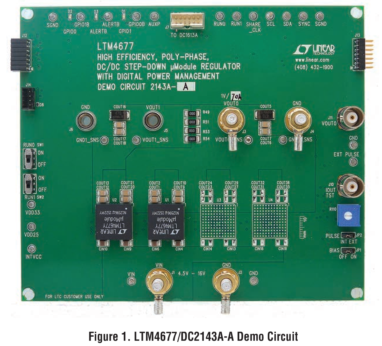
- LTM4677 Demo Circuit - High Current, Parallel µModule Buck Regulators with Power System Management (5.75-16V to 1V @ 72A)
- LTM4677 Demo Circuit - High Current, Parallel µModule Buck Regulators with Power System Management (5.75-16V to 1V @ 108A)
- LTM4677 Demo Circuit - High Current, Parallel µModule Buck Regulators with Power System Management (5.75-16V to 1V @ 144A)
- LTM4677 & LTM4650 Demo Circuit - High Current, Parallel µModule Buck Regulators with Power System Management (4.5-16V to 1V @186A)
- LTM4677 & LTM4650 Demo Circuit - High Current, Parallel µModule Buck Regulators with Power System Management (4.5-16V to 1V @ 86A)
下記製品はLTspiceで使用することが出来ます。:
- LTM4677
Linduino 2
LTpowerCAD 1
次のデバイス用の設計ツールがLTpowerCADでご使用になれます。
- LTM4677
LTpowerPlay®
LTpowerPlay® は、旧リニアテクノロジーのデジタル・パワー・マネージメント(PSM)製品をサポートする強力なWindowsベースの開発環境です。
ツールを開く
LTspice®は、無料で提供される強力で高速な回路シミュレータと回路図入力、波形ビューワに改善を加え、アナログ回路のシミュレーションを容易にするためのモデルを搭載しています。
Linduino はアナログ・デバイセズの Arduino 互換システムで、アナログ・デバイセズ製集積回路のファームウェア・ライブラリおよびサンプル・コードの開発と配布に使用します。Linduino対応の各製品には、LTSketchbook/Part Numberフォルダに定義されたサンプルのメイン・プログラムと、LTSketchbook/librariesフォルダに定義されたドライバ・コードが含まれています。
LTpowerCAD®は、電力段のデバイスの選択、詳細な電力効率の提供、ループのボーデ線図の安定性および負荷過渡応答解析の敏速な表示などを行うと共に、シミュレーション用にLTspiceにエクスポートできる電源設計プログラムです。
評価用キット


LTM4677 and LTM4650 Demo Board | Step-Down μModule Regulator with PMBus Power System Management LTM4677 + LTM4650, 86A
資料

LTM4675 + LTM4676A + LTM4677 + LTM4620A Demo Board | PSM μModule Power Stick
資料
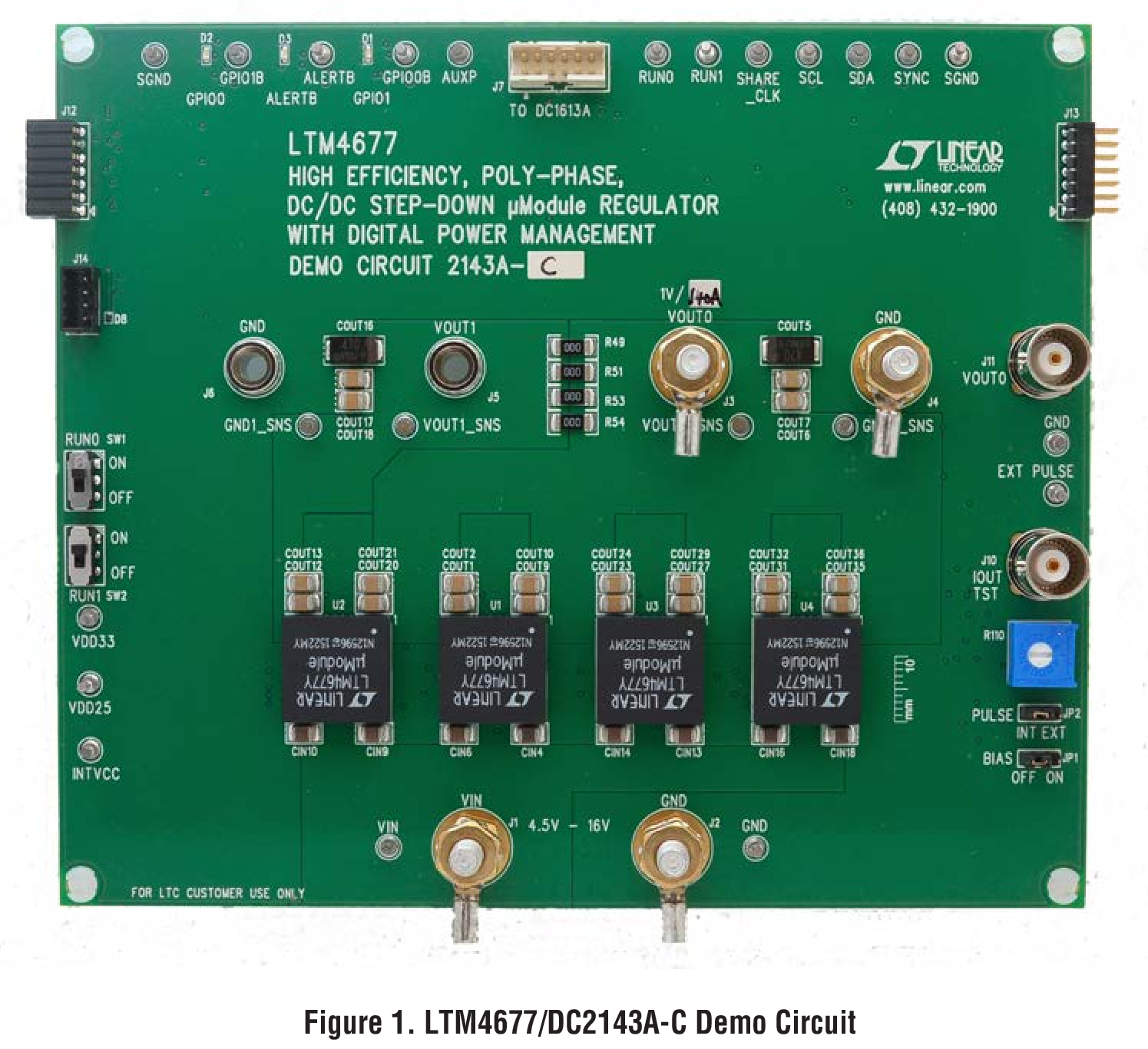
LTM4677 Demo Board | µModule PMBus Buck, LTM4677(x4), 4.5V ≤ VIN ≤ 16V, VOUT = 0.5V to 1.8V @ 144A
資料
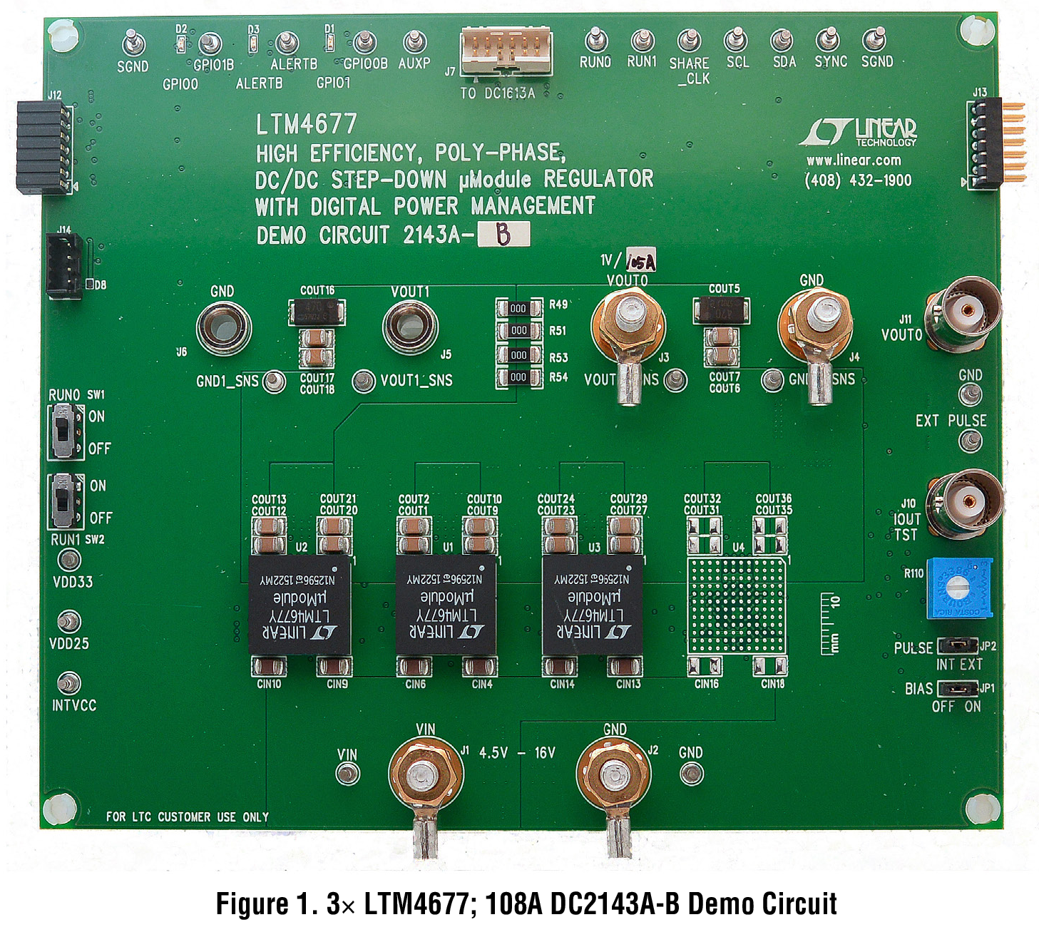
LTM4677 Demo Board | µModule PMBus Buck, LTM4677(x3), 4.5V ≤ VIN ≤ 16V, VOUT = 0.5V to 1.8V @ 108A
資料

LTM4677/LTM4650 Demo Board | Buck μModule Regulator with Digital PSM, LTM4677 + LTM4650, 4.5V ≤ VIN ≤ 16V, VOUT = 0.5V to 1.8V @ 86A
資料
LTM4677 Demo Board | 2x LTM4677 Buck μModule with Digital PSM, 4.5V ≤ VIN ≤ 20V, VOUT = 0.5V to 1.8V @ 72A
資料
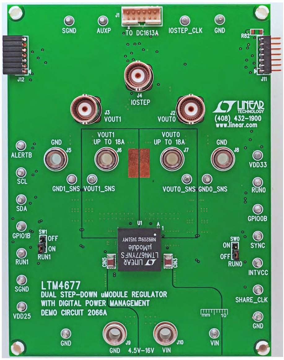
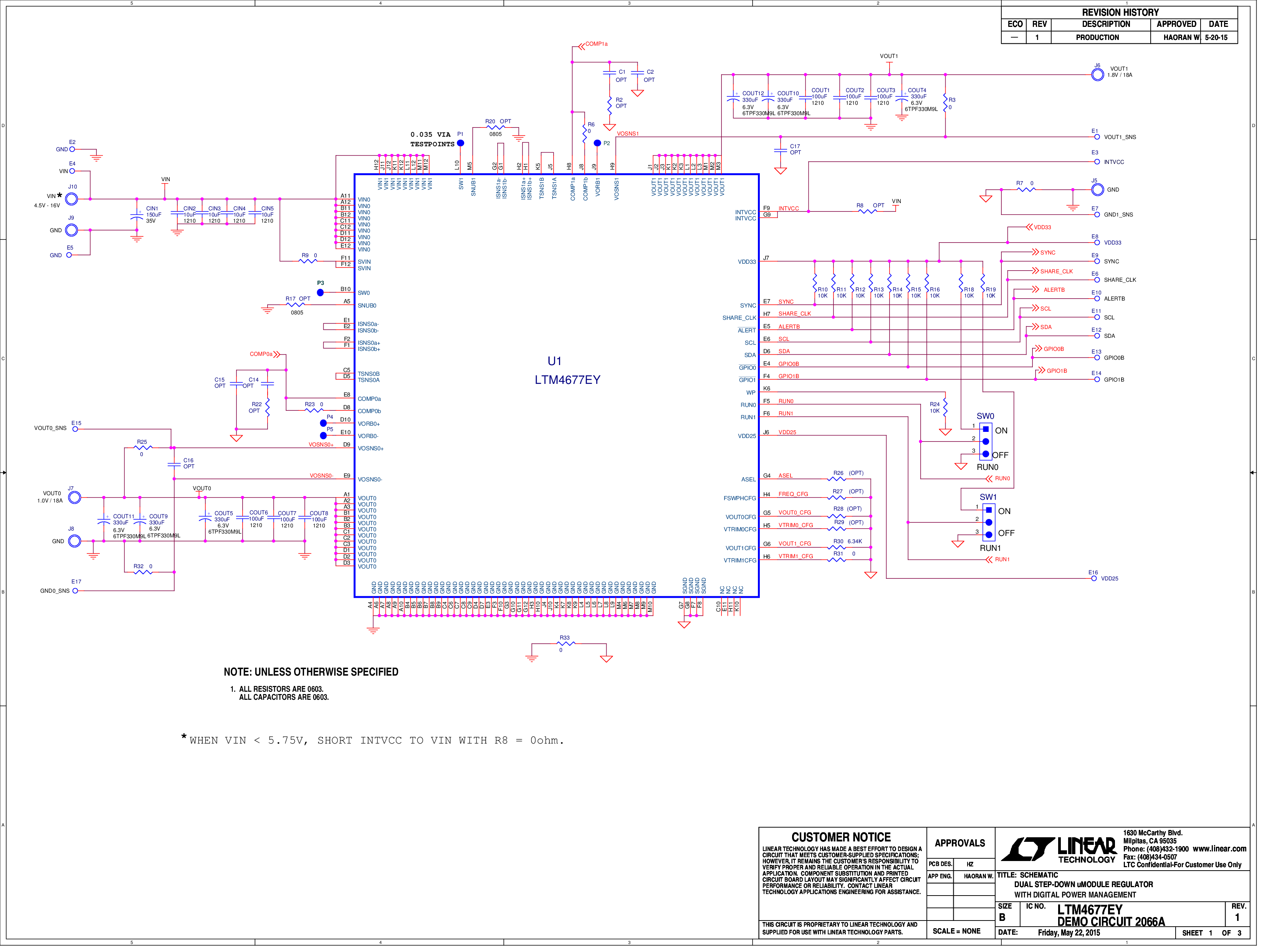
LTM4677EY Demo Board | μModule Regulator With Digital PSM, 4.5V ≤ VIN ≤ 16V, VOUT0 = VOUT1 = 0.5V to 1.8V @ 18A
資料


LTM4677/LTM4650 Demo Board | Buck μModule Regulator with Digital PSM, LTM4677 + LTM4650(x3), 4.5V ≤ VIN ≤ 16V, VOUT = 0.5V to 1.8V @ 186A
資料
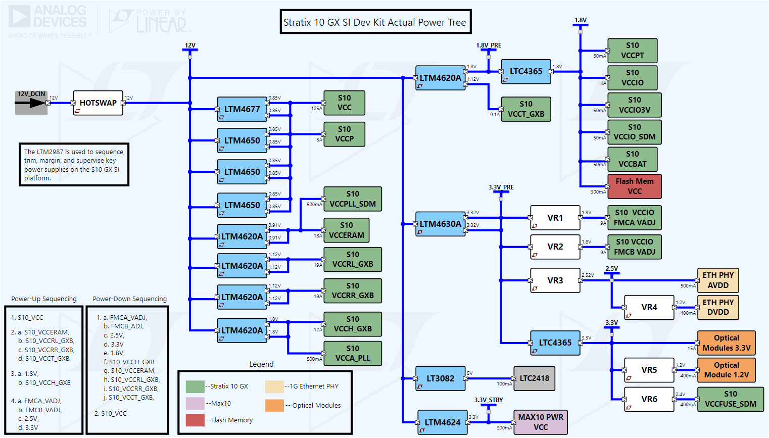
リファレンス・デザイン


使用製品
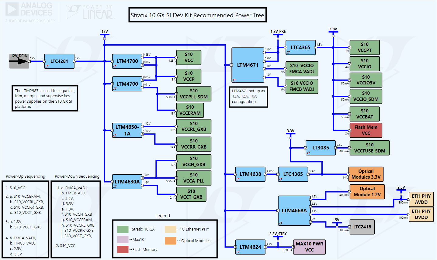
使用製品
使用製品
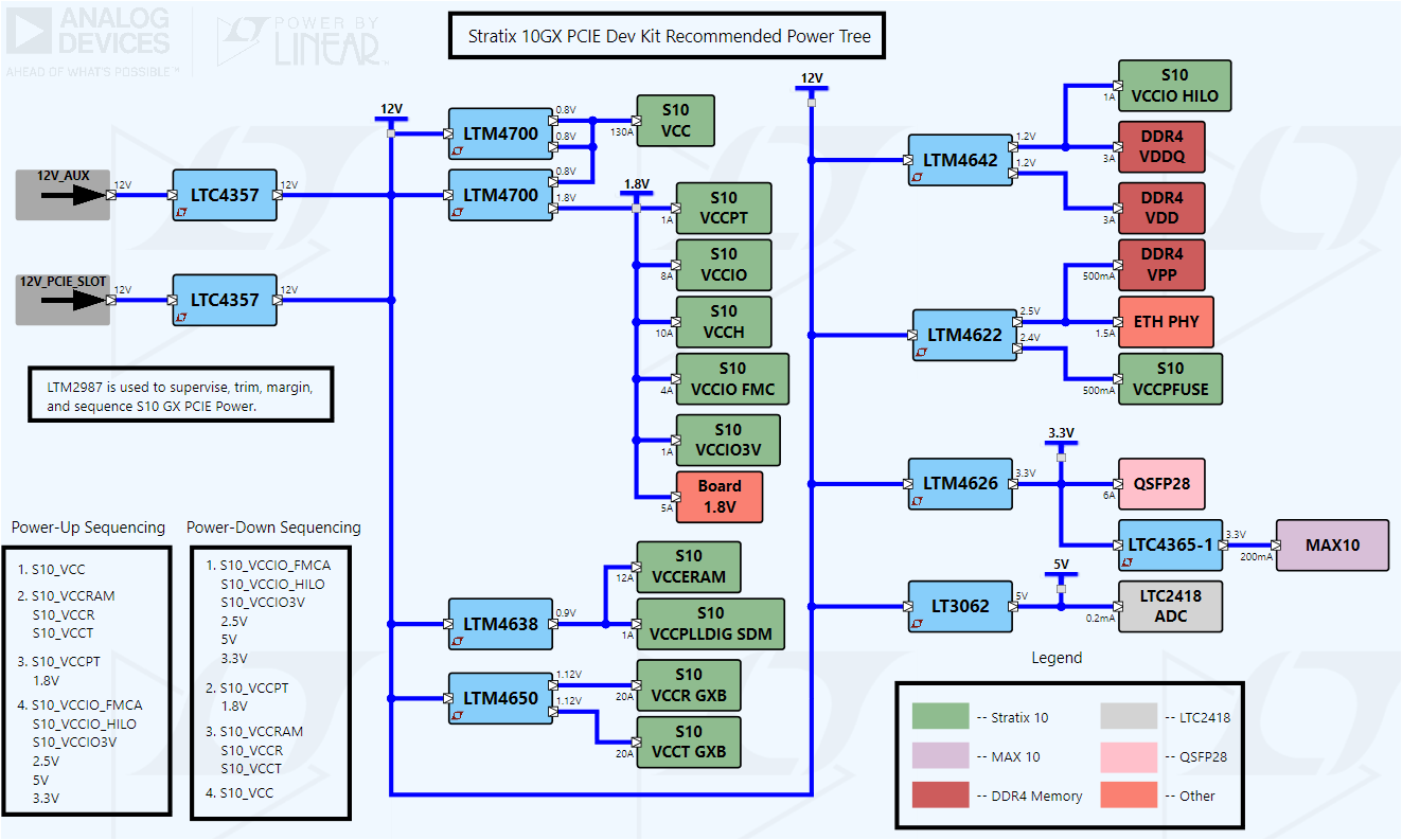
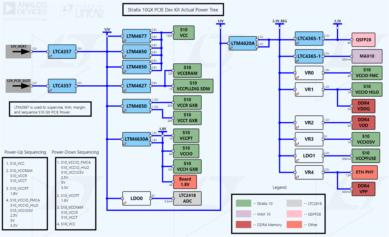
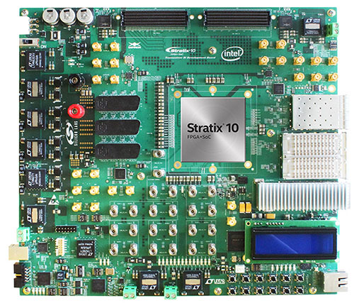
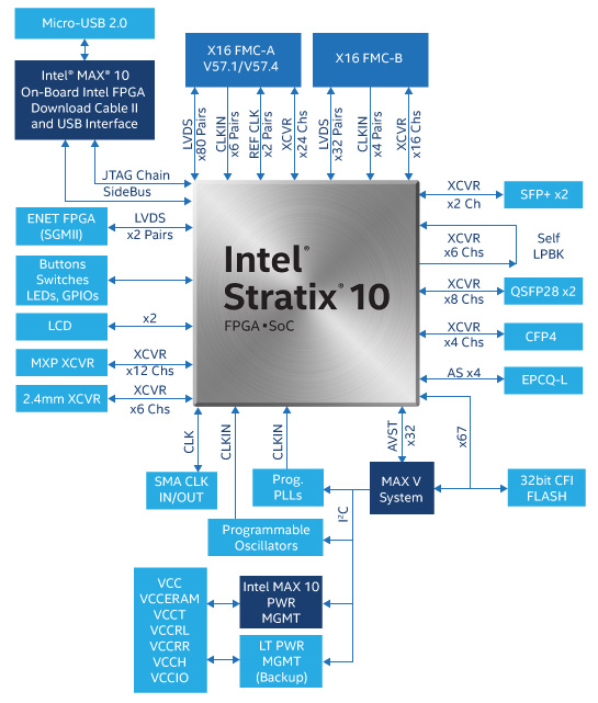
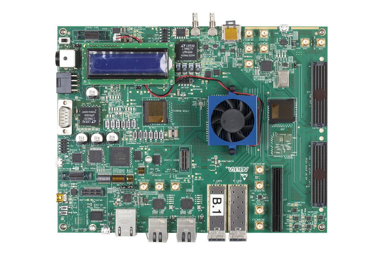
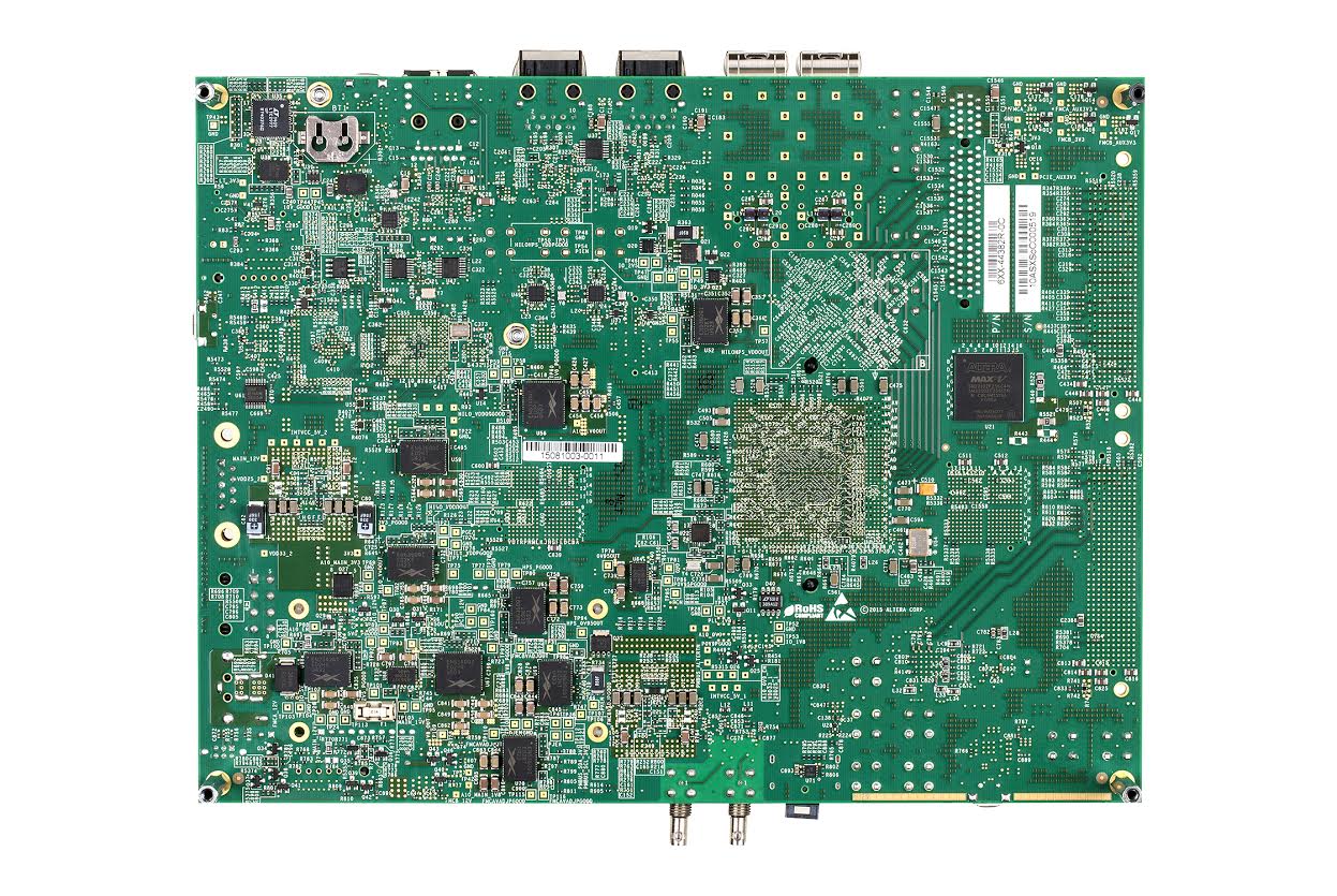
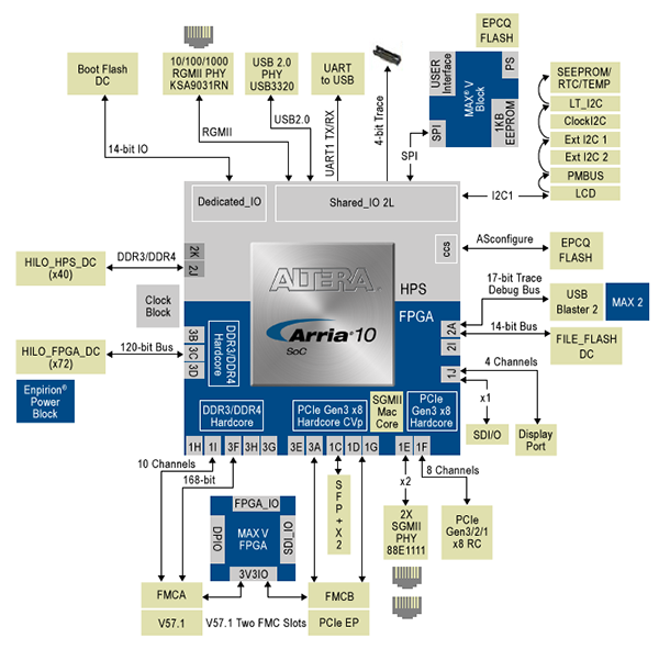
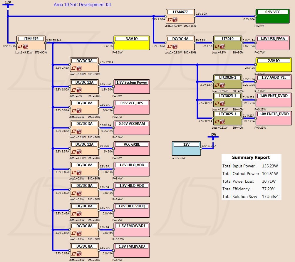
Altera FPGA