ADP2301
新規設計に推奨ステップダウン・スイッチング・レギュレータ、1.2 A、20 V
- 製品モデル
- 2
- 1Ku当たりの価格
- 最低価格:$0.95
製品の詳細
|
|
ADP2300/ADP2301は、小型、一定周波数、電流モードのステップダウンDC-DC安定化電源で、パワーMOSFETを内蔵しています。 ADP2300/ADP2301は3.0V~20Vのいかなる入力電圧でも動作しますので、幅広いアプリケーションに適応します。正確な低電圧の内部リファレンスを備えていますので、これらのデバイスは、±2%精度で最大1.2Aの負荷電流を備えた、0.8Vの低い安定化出力電圧を発生させるのに相応しいデバイスといえます。
これらのデバイスには2つの周波数オプションがあります。ADP2300は700kHzで動作し、ADP2301は1.4MHzで動作します。このようなオプションがありますので、ユーザはトータル・ソリューションとして、効率と大きさの間のトレードオフに基づいて使用の決定ができます。電流モードの制御は、高速で安定な電圧および負荷トランジエント性能を提供します。各ADP2300/ ADP2301製品は、内部にソフトスタート機能を内蔵しており、パワーアップ時の突入電流を防止します。その他の特長として、短絡回路保護機能、サーマル・シャットダウン(TSD)機能、入力の超低電圧ロックアウト(UVLO)機能(入力電圧が一定電圧以下になった場合に出力を停止させる機能)などがあります。高精度なイネーブル・ピンのスレショールド電圧によって、ADP2300/ ADP2301は、容易に他の入/出力電源からのシーケンシング(他の電源出力がスレショールド電圧以下になった場合にADP2300/ ADP2301を立ち上げる機能)が可能となります。あるいは、イネーブル・ピンを、抵抗デバイダーを使うことによって、プログラマブルなUVLO入力として使うこともできます。
ADP2300/ ADP2301は、6ピンTSOPパッケージを採用し、-40℃~+125℃の温度範囲にわたって性能が仕様規定されています。
アプリケーションドキュメント
データシート 2
ユーザ・ガイド 1
アプリケーション・ノート 2
技術記事 2
電源リファレンス・デザイン 1
リファレンス設計 2
| 製品モデル | ピン/パッケージ図 | 資料 | CADシンボル、フットプリント、および3Dモデル |
|---|---|---|---|
| ADP2301AUJZ-R2 | 6-Lead TSOT | ||
| ADP2301AUJZ-R7 | 6-Lead TSOT |
| 製品モデル | 製品ライフサイクル | PCN |
|---|---|---|
|
1 26, 2010 - 10_0007 Halogen Free Material Change for TSOT Products |
||
| ADP2301AUJZ-R7 | 製造中 | |
これは最新改訂バージョンのデータシートです。
ソフトウェア・リソース
必要なソフトウェア/ドライバが見つかりませんか?
ドライバ/ソフトウェアをリクエストツールおよびシミュレーション
LTspice
下記製品はLTspiceで使用することが出来ます。:
- ADP2301
ADP230x Inverting Buck-Boost Regulator Design Tool
Microsoft Excel download tool from ADIsimPower to generate a power supply design complete with a schematic, bill of materials, and performance specifications.
ツールを開くADP230x Buck Regulator Design Tool
Microsoft Excel download tool from ADIsimPower to generate a power supply design complete with a schematic, bill of materials, and performance specifications.
ツールを開く
LTspice®は、無料で提供される強力で高速な回路シミュレータと回路図入力、波形ビューワに改善を加え、アナログ回路のシミュレーションを容易にするためのモデルを搭載しています。
評価用キット

OBSOLETE: AD-FMCMOTCON2-EBZ Evaluation Board
資料
ソフトウェア
ADP2301 評価用ボード
資料
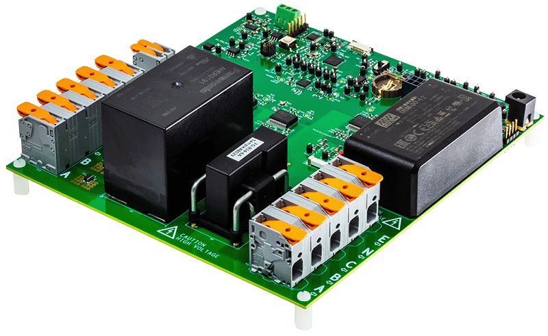
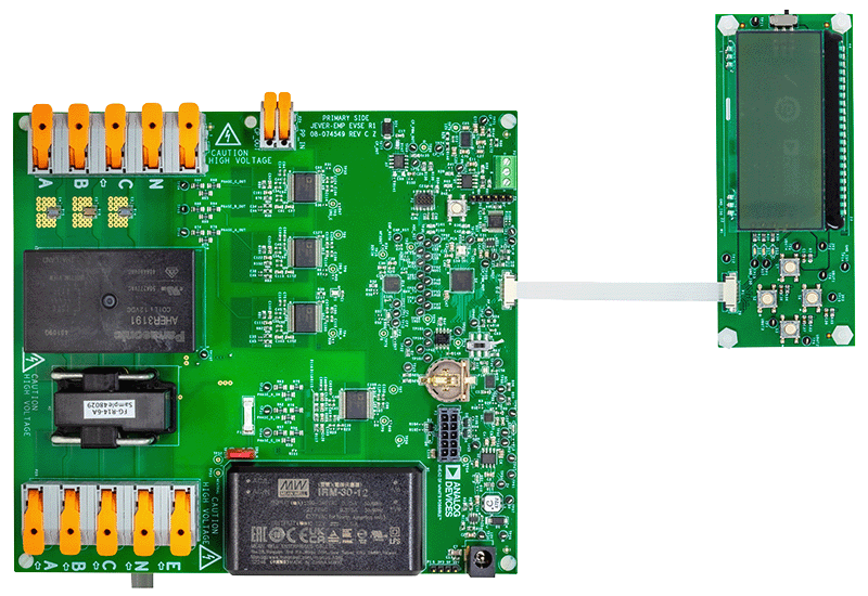
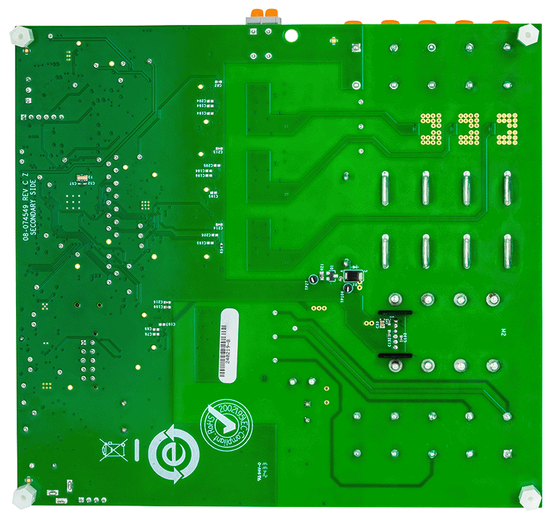
AD-ACEVSE22KWZ-KIT


