ADP1621
製造中ステップアップDC/DCコントローラ、固定周波数、電流モード
- 製品モデル
- 1
- 1Ku当たりの価格
- 最低価格:$1.77
製品の詳細
- 92%の高効率(センス抵抗は不要)
- ±1.0%の初期精度
- IC供給電圧範囲:2.9~5.5V
- 最低1.0Vの入力電圧
- 外付けのNPNまたは抵抗で高い入力電源電圧が可能(>5.5V)
- VINUVLOおよび35mAシャント・レギュレータ
- 1本の外部抵抗によるスロープ補償
- プログラマブルな動作周波数(100kHz~1.5MHz)、1本の抵抗を使用
- ロスレス・モード時のスイッチノード電圧:<30V
- 抵抗センス・モード時のスイッチノード電圧:>30V
- 外部クロックに同期可能
- 電流モード動作で優れたラインおよび負荷過渡応答を実現
ADP1621は、固定周波数、パルス幅変調(PWM)、電流モードのステップアップ・コンバータ・コントローラです。外付けのnチャンネルMOSFETを駆動して、入力電圧をより高い出力電圧に変換します。また、フライバック回路、SEPIC回路、およびフォワード・コンバータ回路(絶縁または非絶縁型)を駆動することもできます。
ADP1621では、n チャンネル MOSFET のオン抵抗両端の電圧降下を測定するため、電流検出用の電力抵抗は不要になります。この製品では、スイッチノードで最大30Vの電圧を使用して、処理効率の最大化とコストの低減を図っています。スイッチノード電圧を30V以上にする場合、あるいはより正確な電流制限を行うには、CSピンをMOSFETのソース内の電流検出用抵抗に接続する必要があります。スロープ補償は外付けの抵抗で実現でき、さまざまなスイッチング周波数、入力電圧、出力電圧に対して、外付け部品(インダクタやMOSFET)を幅広く選択できます。
ADP1621の入力電源電圧範囲は2.9~5.5Vです。小信号用NPNトランジスタ又は抵抗1つを使用すると、より高い入力電圧で使うことが可能です。燃料電池のアプリケーションの場合、入力電源電圧は1Vまで下げられます。スイッチング周波数は100kHz~1.5MHzの範囲で外付け抵抗によって設定でき、SDSNピンを使って外部クロックに同期させることができます。シャットダウン静止電流は10μA以下です。この製品に内蔵されているサーマル・シャットダウン機能は、ジャンクション温度が約150℃になったときにゲート・ドライバをシャットダウンします。内蔵のソフトスタート回路は、スタートアップ時の突入電流を防止します。ADP1621は鉛フリーの10ピンMSOPパッケージを採用しており、-40~+125℃のジャンクション温度範囲で仕様規定されています。
アプリケーション
- APDバイアス
- 携帯用電子機器
- 絶縁型DC/DCコンバータ
- ステップアップ/ステップダウンDC/DCコンバータ
- ラップトップ・コンピュータおよびナビゲーション・システム
- LCDバックライト用LEDドライバ
ドキュメント
データシート 1
アプリケーション・ノート 2
技術記事 3
評価用設計ファイル 1
よく聞かれる質問 1
ビデオ 1

リファレンス設計 1
電源リファレンス・デザイン 3
| 製品モデル | ピン/パッケージ図 | 資料 | CADシンボル、フットプリント、および3Dモデル |
|---|---|---|---|
| ADP1621ARMZ-R7 | 10-Lead MSOP |
| 製品モデル | 製品ライフサイクル | PCN |
|---|---|---|
|
3 22, 2021 - 21_0001 Addition of Amkor Philippines as an Alternate Site for Singulated MSOP and MSOP_EP |
||
| ADP1621ARMZ-R7 | 製造中 | |
|
10 30, 2017 - 15_0176 Assembly Transfer of Select 8/10L MSOP Products to Amkor Philippines |
||
| ADP1621ARMZ-R7 | 製造中 | |
|
10 7, 2015 - 15_0199 ADP1621 Datasheet Specification Change |
||
| ADP1621ARMZ-R7 | 製造中 | |
|
5 15, 2012 - 10_0006 Halogen Free Material Change for mini SOIC Products |
||
| ADP1621ARMZ-R7 | 製造中 | |
|
12 21, 2009 - 06_0159 Qualification of 8" S6 wafer fab process at Analog Devices, Limerick, Ireland. |
||
| ADP1621ARMZ-R7 | 製造中 | |
これは最新改訂バージョンのデータシートです。
ソフトウェア・リソース
必要なソフトウェア/ドライバが見つかりませんか?
ドライバ/ソフトウェアをリクエストツールおよびシミュレーション
LTspice
下記製品はLTspiceで使用することが出来ます。:
- ADP1621
ADP1621 Cuk Design Tool
Microsoft Excel download tool from ADIsimPower to generate a power supply design complete with a schematic, bill of materials, and performance specifications.
ツールを開くADP1621 Coupled-SEPIC Design Tool
Microsoft Excel download tool from ADIsimPower to generate a power supply design complete with a schematic, bill of materials, and performance specifications.
ツールを開くADP1621 Boost Regulator Design Tool
Microsoft Excel download tool from ADIsimPower to generate a power supply design complete with a schematic, bill of materials, and performance specifications.
ツールを開くSIMPLISモデル 1
LTspice®は、無料で提供される強力で高速な回路シミュレータと回路図入力、波形ビューワに改善を加え、アナログ回路のシミュレーションを容易にするためのモデルを搭載しています。
評価用キット


Isolated Inverter Platform Evaluation Board
ソフトウェア

OBSOLETE: AD-FMCMOTCON2-EBZ Evaluation Board
資料
ソフトウェア
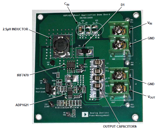
ADP1621 Evaluation Board
資料
リファレンス・デザイン


ADRV-PACKRF Robust Portable Radio Design
使用製品
設計および組み込みツール


完全絶縁型の4チャンネル多重化 HARTアナログ出力回路 ※Rev.0を翻訳したものです。最新版は英語資料をご覧ください。
使用製品
設計および組み込みツール


高安定性の絶縁型エラーアンプを使用した フライバック電源 ※Rev.0を翻訳したものです。最新版は英語資料をご覧ください。