LT3960

新規設計に推奨

I2C to CAN-Physical Transceiver

製品モデル
8
1Ku当たりの価格
最低価格:$2.02
利用上の注意

アナログ・デバイセズ社は、提供する情報が正確で信頼できるものであることを期していますが、その情報の利用に関して、あるいはその利用によって生じる第三者の特許やその他の権利の侵害に関して一切の責任を負いません。また、アナログ・デバイセズ社の特許または特許の権利の使用を明示的または暗示的に許諾するものでもありません。仕様は予告なしに変更する場合があります。本紙記載の商標および登録商標は、各社の所有に属します。


本データシートの英語以外の言語への翻訳はユーザの便宜のために提供されるものであり、リビジョンが古い場合があります。最新の内容については、必ず最新の英語版をご参照ください。

なお、日本語版のデータシートは基本的に「Rev.0」(リビジョン0)で作成されています。そのため、英語版が後に改訂され、複数製品のデータシートがひとつに統一された場合、同じ「Rev.0」の日本語版のデータシートが異なる製品のデータシートとして表示されることがあります。たとえば、「ADM3307E」の場合、日本語データシートをクリックすると「ADM3311E」が表示されます。これは、英語版のデータシートが複数の製品で共有できるように1本化され、「ADM3307E/ADM3310E/ADM3311E/ADM3312E/ADM3315E」(Rev.G)と改訂されたからで、決して誤ってリンクが張られているわけではありません。和文化されたデータシートを少しでも有効に活用していただくためにこのような方法をとっておりますので、ご了解ください。

Viewing:

製品の詳細

  • Protected from Overvoltage Line Faults to ±40V
  • Up to 400kbps I2C Communications
  • 4V to 60V Power Supply Range with Internal 3.3V Regulator
  • 3.3V or 5V Bus Voltage
  • Extended Common Mode Range (±36V)
  • Current Limited Drivers with Thermal Shutdown
  • Power-Up/Down Glitch Free Driver Outputs
  • Low Current Shutdown Mode
  • Transmit Data Dominant Timeout Function
  • E- and J-Grades Available
  • Available in a 10-Lead MSOP Package
  • AEC-Q100 Qualified for Automotive Applications
LT3960
I2C to CAN-Physical Transceiver
LT3960 Application Circuit LT3960 Performance Graph LT3960 Pin Configuration
myAnalogに追加

myAnalogの製品セクション(通知受け取り)、既存/新規プロジェクトに製品を追加する。

新規プロジェクトを作成
質問する
サポート

アナログ・デバイセズのサポート・ページはアナログ・デバイセズへのあらゆるご質問にお答えするワンストップ・ポータルです。


ドキュメント

さらに詳しく
myAnalogに追加

myAnalogの製品セクション(通知受け取り)、既存/新規プロジェクトに製品を追加する。

新規プロジェクトを作成

評価用キット

eval board
DC2686A

LT3960 and LT3967 Demo Board | 1.3A 8-Switch Matrix LED Dimmer with I2C to CAN-Physical Layer Transceiver

製品詳細

Demonstration circuit 2686A is a 1.3A 8-switch matrix LED dimmer system with an I2C to CAN-physical transceiver featuring the LT3967 and LT3960. This demonstration circuit connects directly to a LED string and LED driver demonstration circuit to allow for independent dimming control of up to 8 channels of LEDs. A Linduino® One demonstration circuit is used to interface with the board and can connect in one of two different ways:

  1. Connect directly to a Linduino One demonstration circuit with a QuikEval ribbon cable.
  2. Connect using the LT3960 break-off board to connect to the I2C master device, but pass data over two twisted pair lines to the LT3960 on the main PCB.

The LT3967 matrix dimmer features 8 individually con-trolled 1.3A rated floating NMOS switch channels and can support up to 56V of LEDs per device. The channels of the LT3967 can be configured for series connections, or non-series connections. Additional DC2686A demo circuits can be connected in series for higher number of LEDs, or in parallel to allow for higher current operation. Resistors are used to configure both the I2C slave address as well as the default start-up state. The default configuration for DC2686A sets the I2C address as 0000 with all LEDs off. See the LT3967 data sheet for details.

The LT3960 I2C to CAN-Physical transceiver is used to send and receive I2C data through harsh or noisy environments at up to 400kb/s using the CAN-Physical layer for differential signaling over twisted pair connections. Both SDA and SCL data lines are converted to differential signals and are shared between devices connected to the bus. This allows for physical separation of the I2C source with the LT3960 transceiver board and the LT3967 main PCB along with the LED driver.

This demo circuit is designed to be easily configured and interfaced with a compatible low output capacitance LED driver and LED string. It can easily be directly attached to a buck LED driver or a floating buck-mode LED driver. More sophisticated setups with series matrix dimmers for higher number of LEDs such as 12 or 16 is possible. Please consult factory applications for details or look for more details on analog.com.

The LT3967 and LT3960 data sheets give complete description of the parts, their operation and applications information. The data sheets must be read in conjunction with the demo manual for demonstration circuit DC2686A. The LT3967EFE is assembled in a thermally enhanced 28-lead TSSOP package. The LT3960EMSE is assembled in a 10-lead MSOP package.

eval board
EVAL-LT3960

LT3960デモ用ボード | I2C-to-CAN物理トランシーバー

製品詳細

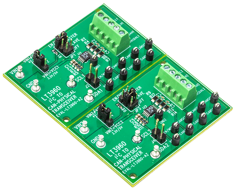
評価用回路EVAL-LT3960-AZは、10ピン・プラスチックMSOPパッケージにLT3960、I2C to CAN物理トランシーバーを搭載しています。EVAL-LT3960-AZは、選択可能なJP1とJP3ジャンパを使ってマスタ・モードとスレーブ・モードで設定された2つのICで構成されています。ボードは中央で簡単に分離され、2つの回路に分かれる設計になっています。

LT3960 I2C-to-CAN物理トランシーバーは、ツイスト・ペア接続を介した差動伝送を行うためのCAN物理層を使用して、過酷でノイズの多い環境でも最高400kbpsでのI2Cデータ送受信を実現します。SDAおよびSCLデータ・ラインの両方を差動信号に変換して、バスに接続されたデバイス間で共有します。これにより、I2CソースとI2Cレシーバーを物理的に分離できます。

1つ目のLT3960がI2Cマスタ(I2C互換のマイクロコントローラ)に接続されます。2つ目のLT3960は、2つのツイスト・ペアで1つ目のLT3960に接続する必要があります。1つまたはそれ以上のI2Cスレーブ・デバイスを使うにはローカルにI2Cバスが必要です。LT3960デバイスは、マスタからスレーブへの一方向のみにクロック信号を送信します。データ信号は常に双方向に通信できます。

LT3960のデータシートには、部品、動作、およびアプリケーションの詳細が記載されています。評価用回路EVAL-LT3960-AZを使用する際は、ユーザー・ガイドと併せてデータシートを参照してください。LT3960EMSEは10ピンMSOPパッケージで組み立てられています。

DC2686A
LT3960 and LT3967 Demo Board | 1.3A 8-Switch Matrix LED Dimmer with I2C to CAN-Physical Layer Transceiver
DC2686A Evaluation Board DC2686A Evaluation Board - Top View DC2686A Evaluation Board - Bottom View
EVAL-LT3960
LT3960デモ用ボード | I2C-to-CAN物理トランシーバー
EVAL-LT3960-AZ - Angle View EVAL-LT3960-AZ - Top View EVAL-LT3960-AZ - Bottom View Quick Start Procedure Setup Drawing for EVAL-LT3960-AZ

最新のディスカッション

最近表示した製品