LT8292
推荐用于新设计60V Low IQ Full-Featured Synchronous Buck-Boost Controller
- 产品模型
- 4
产品详情
- 4-Switch Single Inductor Architecture that Allows VIN Above, Below, or Equal to VOUT
- Proprietary Buck-Boost Peak Current Mode
- Low Ripple Burst Mode: 30μA IQ
- Forced Continuous Mode or Pulse-Skipping Operation
- Split Gate Driver Outputs
- Selectable Dead Time Settings
- Leaderless Current Sharing
- Adjustable and Phase-lockable: 100kHz to 650kHz
- Spread Spectrum Frequency Modulation
- ±2% Output Voltage Accuracy: 1V ≤ VOUT ≤ 60V
- ±5% Input or Output Average Current Accuracy
- Integrated Bootstrap Diodes
- VOUT Disconnected from VIN During Shutdown
- 38-Lead Thin Shrink Small Outline Package (TSSOP) with Exposed Pad
- Automotive Qualified
LT8292 is a synchronous 4-switch buck-boost controller that regulates output voltage and output or input current from an input voltage above, below, or equal to the output voltage. The proprietary buck-boost peak current mode architecture allows adjustable and phase-lockable 100kHz to 650kHz fixed frequency operation, or internal spread spectrum operation for low electromagnetic interference (EMI). When the output is regulated above 5V, the LT8292 can operate from an input supply as low as 3V after start-up.
The low quiescent current at no-load extends operating run time in battery-powered systems. At light load, either forced continuous, pulse-skipping, or low-ripple Burst Mode can be selected.
The LT8292 features split pull-up/pull-down gate drivers and four selectable dead time settings with shootthrough protection, which allows both optimized efficiency and EMI. Fault protection is also provided to detect output short-circuit conditions, during which the LT8292 runs in low-duty cycle auto-retry mode.
APPLICATIONS
- Automotive, Industrial, Telecom Systems
- General Purpose Buck-Boost Power Supplies
- High-Power Battery-Powered Systems
参考资料
数据手册 1
用户手册 1
ADI 始终高度重视提供符合最高质量和可靠性水平的产品。我们通过将质量和可靠性检查纳入产品和工艺设计的各个范围以及制造过程来实现这一目标。出货产品的“零缺陷”始终是我们的目标。查看我们的质量和可靠性计划和认证以了解更多信息。
| 产品型号 | 引脚/封装图-中文版 | 文档 | CAD 符号,脚注和 3D模型 |
|---|---|---|---|
| LT8292AFE#PBF | 38-Lead TSSOP w/ EP | ||
| LT8292AFE#TRPBF | 38-Lead TSSOP w/ EP | ||
| LT8292AFE#WPBF | 38-Lead TSSOP w/ EP | ||
| LT8292AFE#WTRPBF | 38-Lead TSSOP w/ EP |
这是最新版本的数据手册
软件资源
找不到您所需的软件或驱动?
申请驱动/软件工具及仿真模型
LTspice 2
- LT8292 - 600W Dual-Phase Buck-Boost Controller Example Circuit
- LT8292 - 300W Single-Phase Buck-Boost Controller Example Circuit
LTpowerCAD
LTpowerCAD中提供以下器件的设计工具:
- LT8292
LTspice®是一款强大高效的免费仿真软件、原理图采集和波形观测器,为改善模拟电路的仿真提供增强功能和模型。
评估套件
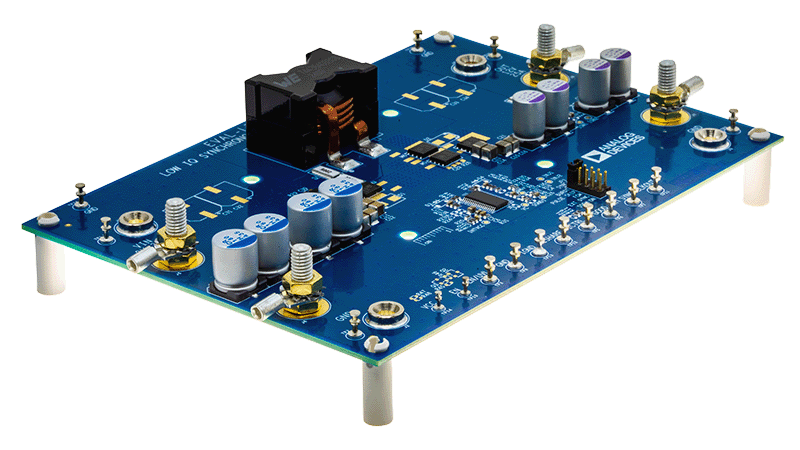
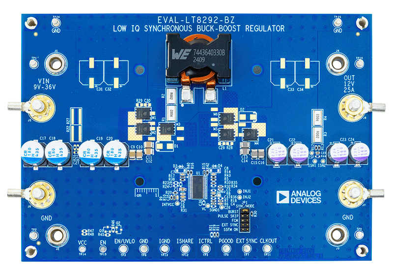
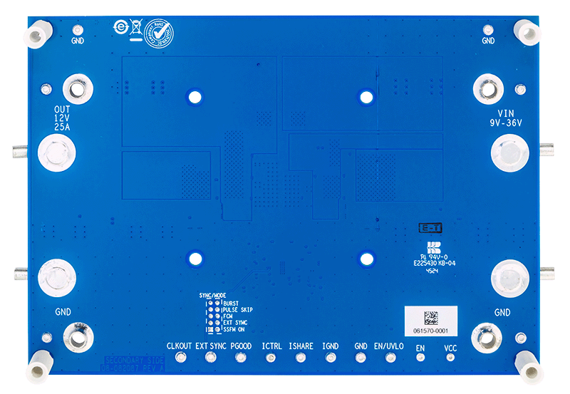
60V 同步降压-升压型控制器
资料
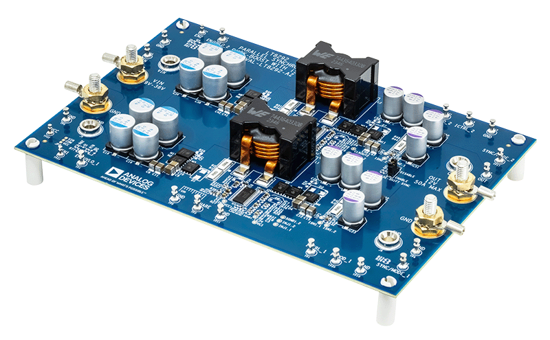
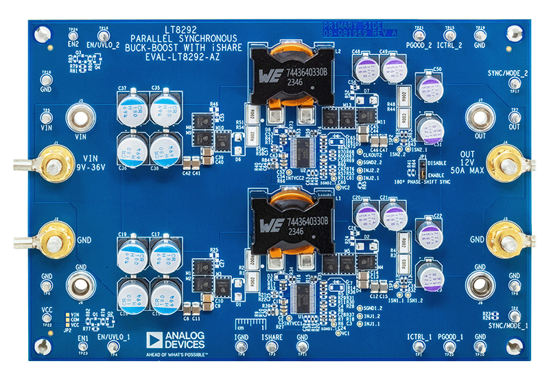
60V Dual-Phase Synchronous Buck-Boost Controller
资料
最新评论
需要发起讨论吗? 没有关于 LT8292的相关讨论?是否需要发起讨论?
在EngineerZone®上发起讨论