Design Note 361: Simple Battery Circuit Extends Power over Ethernet (PoE) Peak Current
Introduction
Power over Ethernet (PoE) is a new development that allows for the delivery of power to Ethernet-based devices via standard Ethernet CAT5 cable, precluding the need for wall adapters or other external power sources. The PoE specification defines a hardware detection protocol where Power Sourcing Equipment (PSE) is able to identify PoE Powered Devices (PDs), thus allowing full backwards compatibility with non-PoE-aware (legacy) Ethernet devices. The PoE specification also sets an upper limit on the power that can be drawn by a PD. The problem is: what happens when a PD must draw more power than allowed by the PoE standard? Examples may be the spin up of a disk drive or a period of sustained transmission of data from an RF transmitter. If the average power load of these applications is less than the available PoE power, one solution is to store power in the PD when power consumption is low and then tap the reserve to augment PoE power when needed. For many applications, a rechargeable battery fits the bill.
Of course, one can’t just throw a battery and a battery charger into the mix. The power path must be able to change seamlessly, on the fly, from PoE-powers-device-and-charges-battery, to PoE-and-battery-power-device, to battery-powers-device. Figure 1 shows a complete and compact solution.
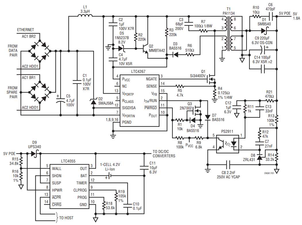
Figure 1. Simple Battery Charger/PowerPath™ Controller (LTC4055) Augments PoE Regulator’s (LTC4267) Peak Output Power to Overcome PoE Power Constraints.
The PoE Circuit
By default, power over the Ethernet is not available. The standard calls for a protocol to be implemented that allows the Ethernet hub to identify the device needing power. The LTC4267simplifies the design of PDs by providing wholesale implementation of the protocol and power management functions.
PoE power comes in the form of –48V at 350mA. If the PoE current is allowed to exceed 400mA, the standard calls for the PSE to break the circuit. This is a problem for devices that occasionally need a little more juice than PoE will offer. Another problem is that –48V does not easily convert to commonly used positive voltage supply rails. Designers are forced to provide DC isolation along with the inverted down conversion to a more usable voltage. To meet these requirements, the LTC4267 used in Figure 1’s circuit implements an input current limited DC input isolated flyback converter, providing a user-settable regulated low voltage.
The LTC4267 circuit in Figure 1 supplies 5V at 1.8A. 5V is a popular supply voltage to run logic, interface with other devices such as USB, and of primary concern in this application, to charge a single Li-Ion cell to its target termination voltage of 4.2V.
PowerPath and Charger Circuit
In Figure 1, the LTC4055 provides triple PowerPath control and Li-Ion battery charging. One path is created by connecting an external Schottky diode to the LTC4055’s OUT pin and the built-in wall adapter detection circuits. In this case, the “wall adapter” power comes from the LTC4267 5V power supply called 5V PoE. The second path is for USB power, not used in this application. The third path is the battery discharge path. When the 5V PoE power goes away or drops out of regulation, the LTC4055 automatically switches the battery power over to the OUT pin using its internal ideal diode circuit. There is no delay in the switchover, so power is never lost.
When 5V PoE power is restored, the battery is disconnected from the load and charging is permitted. The LTC4055 charge current is adjustable and in Figure 1, the circuit is limited to 900mA which is drawn from the OUT pin. That leaves 900mA to run the system while charging. Powered devices connected to the OUT pin must be compatible with the Li-Ion voltage range. The ACPR pin of the LTC4055 can be used to indicate which power source is providing power, allowing the PD to configure itself accordingly.
High Transient Load or Continuous Current Load Operation
When the power limit of the 5V PoE supply is reached, the voltage drops and the battery charger shuts down to relieve the PSE of the charge current load. If the voltage continues to collapse, the battery automatically is placed into parallel operation with the 5V PoE power supply, thus increasing the available peak load current. The LTC4055 ACPR signal is active high during the overload. Battery charging automatically resumes once the overload goes away and the 5V PoE voltage has risen enough to show recovery.
Optimization Options
If sustained currents approaching 1.8A are expected from the 5V PoE and there are thermal management issues related to the diode's heat dissipation, the diode D9 can be replaced with the LTC4411 ideal diode for more efficient operation. Recommended DC/DC converters to generate logic supplies in this application include the LTC3443 buck-boost and/or the LTC3407-2 dual buck regulators.
Conclusion
The highly integrated LTC4267 and LTC4055 simplify the design of compact, simple and complete battery-based power systems that run from Ethernet power. More importantly, seamless PowerPath control enables circuits that can use a battery to augment Ethernet power when an application momentarily demands more than the PoE standard allows.
著者
