Power Management

- µModule Regulators
- Battery Management
- Current Sources
- Display Control and Power
- Energy Harvesting
- Inductorless (Charge Pump) DC/DC Converters
- LDO Linear Regulators
- LED Driver IC
- PMIC and Multifunction
- Smart Power Stages (FET and FET Driver)
- Supercapacitor Chargers
- Switching Regulators
- Ultralow Noise Regulators
- Xenon Photoflash Charger
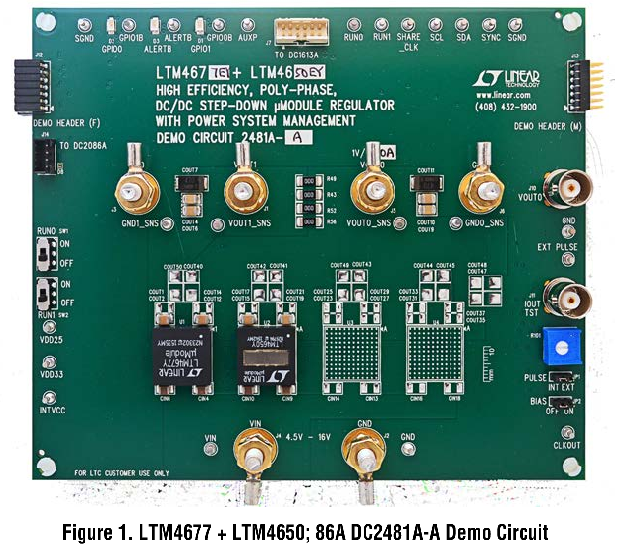
LTM4650