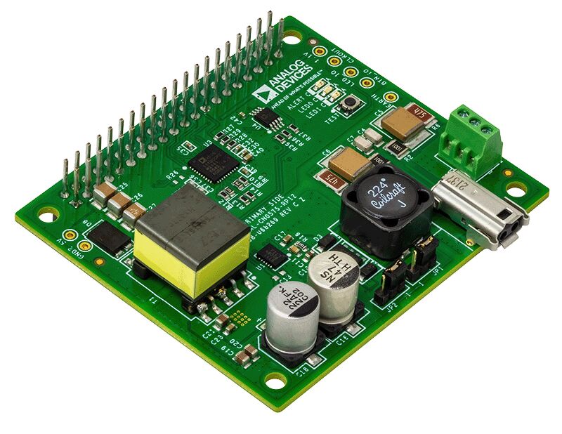
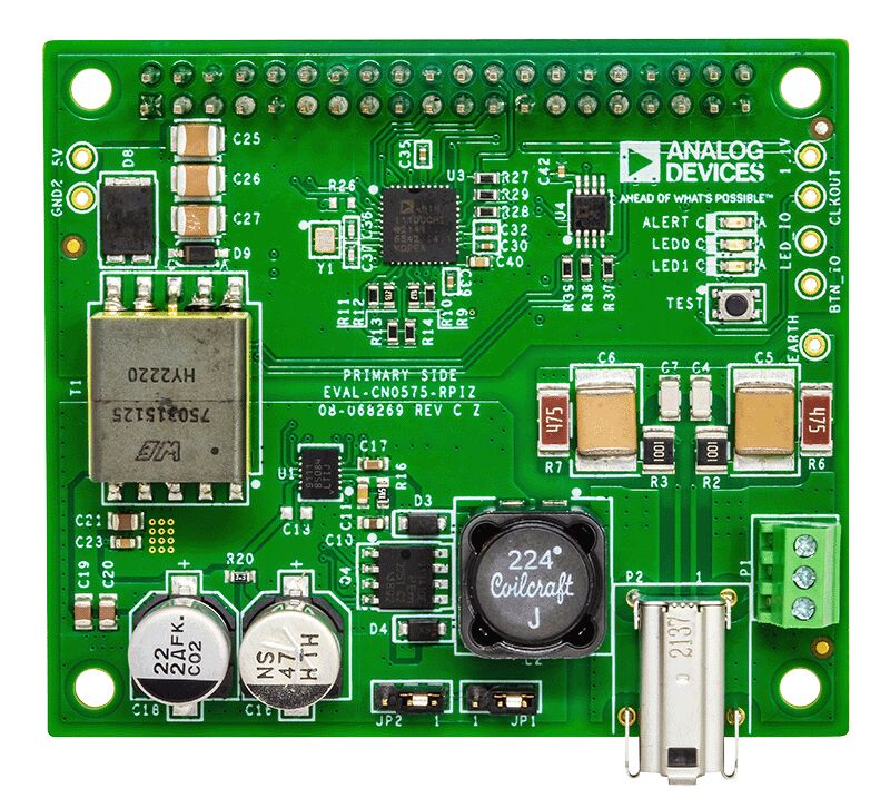
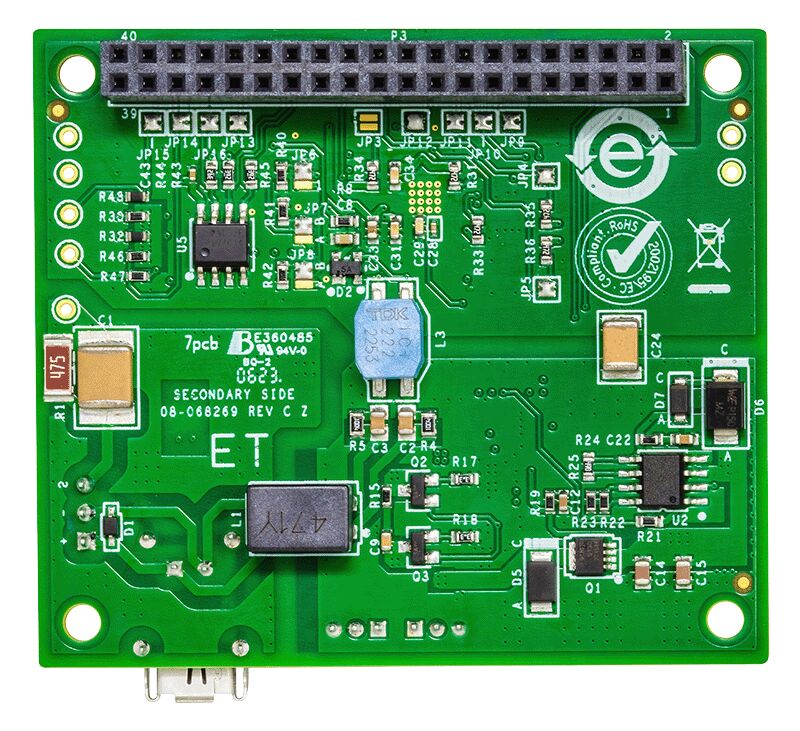
The AD-SWIOT1L-SL provides a complete software and hardware platform for prototyping intelligent, secure, network capable field devices.
The design incorporates the AD74413R Quad-Channel, Software Configurable Input and Output and the MAX14906 Quad-Channel Industrial Digital Output/Digital Input ICs, allowing the multiplexing of several analog and digital functions on four channels which can be independently configurable through software to act as:
- voltage output / input
- current output / input
- digital input / output
- RTD measurement
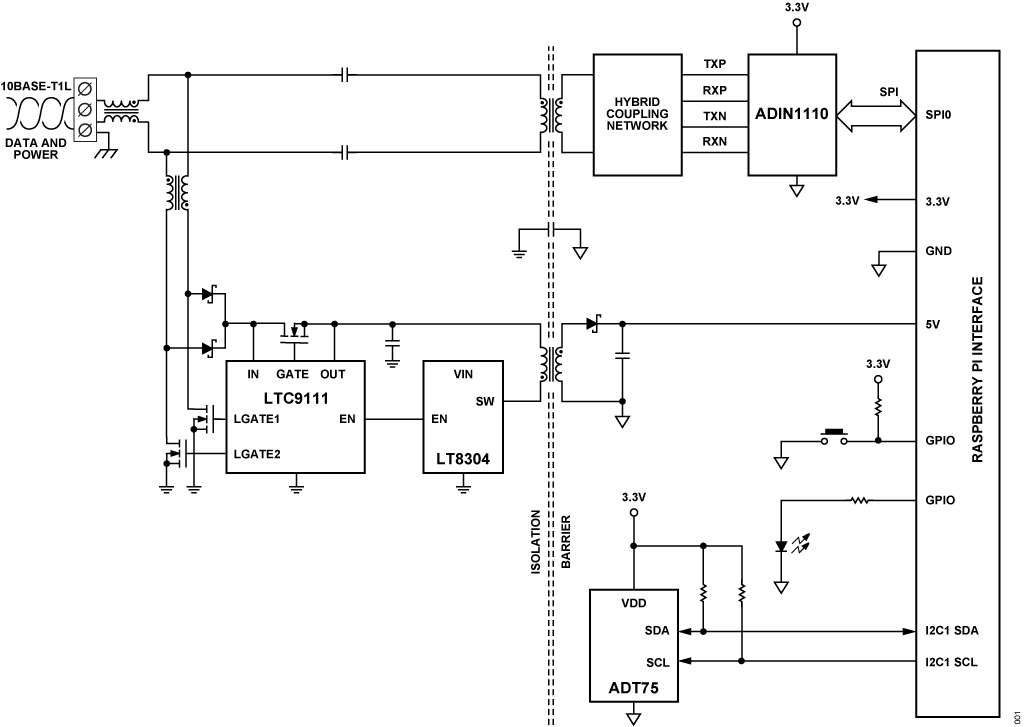
A 10 Mbps single-pair Ethernet link, using the ADIN1110 10BASE-T1L MAC/PHY, enables remote data acquisition and device configuration. The 10BASE-T1L interface can also be used for powering the system via the Single-pair Power over Ethernet (SPoE) technology using the LTC9111 Powered Device (PD) controller. This way, power and data for the system is provided over the same cable to significantly simplify the cabling infrastructure and cost.
For applications requiring high current capabilities, the system can be powered from an external 24 V supply and up to 1.2 A can be output on any of the channels configured as digital outputs. The power supply solution also includes the ADP1032 high performance, isolated micropower management unit (PMU) to provide power and digital control for software configurable I/O devices in one of the most compact formats. The LT8304 Micropower No-Opto Isolated Flyback Converter completes the power tree to provide isolated power to the digital part of the design.
The on-board MAX32650 Ultralow Power ARM® Cortex®-M4 Microcontroller exposes all the necessary debug and programming features to enable a complete software development experience with the system. It is coupled with a 1 Gb (128 MB) external RAM and a 64 Mb (8 MB) external flash memory to meet the most demanding applications and provide the flexibility to implement any protocol stack. Security features are enabled by the MAXQ1065 security coprocessor.
The system is accompanied by an open-source software stack and associated collateral, enabling a complete experience from evaluation and prototyping all the way to production firmware and applications development. An external programmer such as the MAX32625PICO MAXDAP Programming Adapter, or any other similar programmer supporting the SWD interface, is required to enable firmware programming and debug. The system’s firmware is based on Analog Devices’ open-source no-OS framework which includes all the tools required for embedded code development and debugging as well as libraries enabling host-side connectivity for system configuration and data transfer over the UART or the 10BASE-T1L interfaces. A PC application with a user-friendly graphical interface is provided to enable easy system configuration and displaying the acquired data in different ways.
Specifications
| I/O |
| Channels |
4 Software Configurable IO channels |
| Digital input |
Type 1 and 3, or Type 2 |
| Digital output |
High-Side (HS) Switch or Push-Pull (PP) Driver |
| Analog input |
Voltage (0 V to 10 V), Current (0 mA to 25 mA) |
| Analog output |
Voltage (0 V to 11 V), Current (0 mA to 25 mA) |
| RTD measurements |
2-wire RTD (0 Ω to 1 MΩ) |
| Computing Resources |
| CPU |
MAX32650 Ultra-Low-Power Arm Cortex-M4
with FPU-Based Microcontroller (MCU) with 3 MB Flash and 1MB SRAM |
| Memory |
1 Gb RAM |
| Storage |
64 Mb QSPI Flash |
| Connectivity |
| Ethernet |
10BASE-T1L |
| Power Supply |
| External power |
24 DC @ 6A |
| Power over Ethernet |
SPoE class 12 |
| Operating Conditions |
| Temperature range |
-25°C to 60°C |


