ADE9178
ADE9178
新規設計に推奨Energy Management DSP with PEN Fault Detection
Energy Management DSP with PEN Fault Detection
- 製品モデル
- 2
- 1Ku当たりの価格
- 最低価格:$3.00
Viewing:
製品の詳細
- Metrology chip for use with any combination of the following AFEs
- Can support up to four ADE9113/ADE9112/ADE9103 daisy-chained ADCs through 4-wire SPI
- Supports up to a total of 12 ADC channels of data
- 4-wire SPI for Host MCU communications up to 25 MHz
- Total active energy calculation
- Class C accuracy (0.5%), supports the following
- MID 2014/32/EU Annex V
- EN 50470-1:2006
- EN 50470-3:2006
- EN 50470-3:2022
- IEC 62052-11:2020
- IEC 62053-21:2020
- OIML G 22:2022
- NIST Handbook 44:2023
- Total apparent energy calculation using filtered RMS
- Energy accumulation, import and export for reverse power/vehicle to grid (V2G) applications
- Basic power quality features
- Short-duration undervoltage or overvoltage (dip/swell) detection
- Short-duration undercurrent or overcurrent (dip/swell) detection
- Line frequency calculation with 10 mHz accuracy
- Angles between phase voltages and currents
- Power-factor calculation
- Configurable phase, gain and offset calibration registers for all ADC channels
- Two configurable calibration frequency (CF) pulse outputs
- Configurable: no load detection
- Phase-sequence detection
- RMS on full cycle, half cycle and filtered RMS on all ADC channels
- Supported frequency range: 45 Hz to 65 Hz
- Four user-programmable interrupt outputs (IRQs)
- PEN open fault detection (BS 7671:2018 Amendment 1:2020)
- Waveform streaming through UART transmit pin
- Datapath multiplexing to allow any ADC data to be used for any data processing path
- Temperature range: −40°C to +105°C
- Available in 5 mm × 5 mm, 40-lead LFCSP package
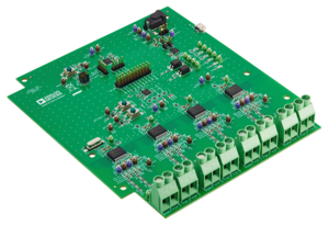
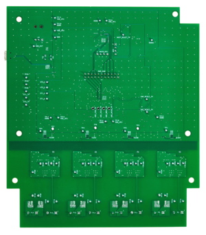
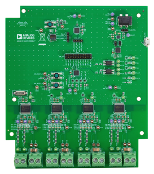
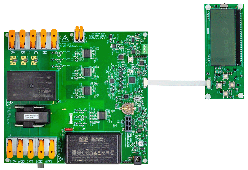
The ADE9178 is a metrology digital signal processor (DSP) for use with a combination of ADE9113/ADE9112/ADE9103 sigma delta analog-to-digital converters (ADCs). The ADE9178 is a high accuracy, 3-phase electrical energy measurement IC primarily for the electric vehicle supply equipment (EVSE) market with serial peripheral interface (SPI) and two flexible pulse outputs. The ADE9178 can interface with up to four daisy-chained ADE9113/ADE9112/ADE9103 devices through SPI protocol. The ADE9178 incorporates all the signal processing required to perform total active energy, apparent energy measurements, and root mean square (RMS) calculations. A fixed function DSP executes this signal processing.
The ADE9178 is well-suited for the EVSE market due to its broad feature set such as protective earth and neutral (PEN) open fault detection without the need for any additional hardware, overcurrent, and overvoltage detection using RMS of half cycle/one cycle and vehicle to grid/home (V2X) capabilities.
The ADE9178 measures active and apparent energy in various 3-phase configurations, such as wye or delta services, with both three and four wires, single phase, and split phase while supporting both 50 Hz and 60 Hz line frequencies. The ADE9178 provides gain, offset, and phase calibration features for each ADC channel. The CF1 and CF2 logic outputs provide power information that is proportional to the measured accumulated energy.
The ADE9178 incorporates some basic power quality measurement features, such as short-duration undervoltage/undercurrent or overvoltage/overcurrent detection, line voltage period measurements, and angles between phase voltages and currents. A Host microcontroller unit (MCU) can be used to communicate with the ADE9178 through 4-wire SPI. Waveform streaming can be accessed by the Host MCU through the WAVEFORM_TX pin of the ADE9178. The ADE9178 also has four user-programmable interrupt pins, IRQ0, IRQ1, IRQ2, and IRQ3, to indicate that an enabled interrupt event has occurred. The ADE9178 is available in a 40-lead, TQFN-EP package.
For more details on how to setup the ADE9178 in an EVSE application, refer to the application note Using ADE9178 for EV Charger Metrology Solution.
Applications
- Electric vehicle supply equipment
- Shunt-based polyphase meters
- Solar inverters
- Energy and power monitoring
ドキュメント
データシート 1
ユーザ・ガイド 2
デバイス・ドライバ 2
| 製品モデル | ピン/パッケージ図 | 資料 | CADシンボル、フットプリント、および3Dモデル |
|---|---|---|---|
| ADE9178GTL+ | Thin Quad Flatpack, No Leads | ||
| ADE9178GTL+T | Thin Quad Flatpack, No Leads |
これは最新改訂バージョンのデータシートです。
ソフトウェア・リソース
ADE9178 driver and EVAL-ADE9178 example code 3
ADE9178 Calibration and Conversion Excel Sheet
評価用ソフトウェア 0
必要なソフトウェア/ドライバが見つかりませんか?
ハードウェア・エコシステム
| 製品モデル | 製品ライフサイクル | 詳細 |
|---|---|---|
| ADE7978 | 製造中 |
3相計量用IC、多相シャント抵抗を使うメータ向け ※英文データシート(Rev.B)に対するエラッタがあります |
評価用キット
資料
ソフトウェア
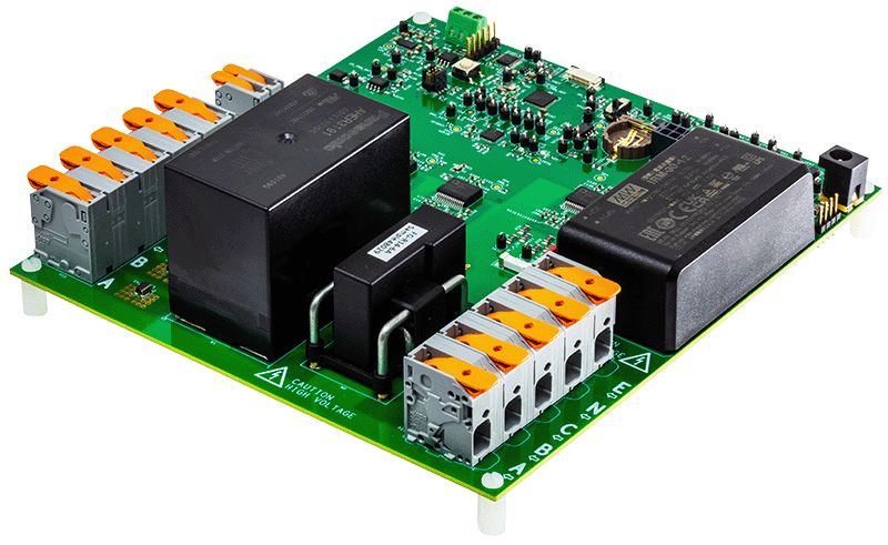
AD-ACEVSE22KWZ-KIT