CN0308


Overview
Design Resources
Design & Integration File
- Schematic
- Bill of Materials
- Gerber Files
- PADS Files
- Assembly Drawing
Evaluation Hardware
Part Numbers with "Z" indicate RoHS Compliance. Boards checked are needed to evaluate this circuit.
- EVAL-ADAS1000SDZ ($234.22) Powering an ECG Front End in Battery Powered Patient Monitoring Applications
- EVAL-SDP-CB1Z ($116.52) Eval Control Board
Device Drivers
Software such as C code and/or FPGA code, used to communicate with component's digital interface.
ADAS1000: Low Power, 5-Electrode Electrocardiogram (ECG) Analog Front End (AFE) Linux Driver
Features & Benefits
- Completely integrated ECG front end
- Low power
- Low noise
Product Categories
Markets and Technologies
-
- Body Temperature Measurement Solutions
- Therapy Device Solutions for Healthcare
- Wearable Health Monitor Solutions
- Oxygen Saturation (SpO2) Measurement Solutions
- Respiration Rate Measurement Solutions
- Non-Invasive Blood Pressure (NIBP) Solutions
- Electrocardiogram (ECG) Measurement Solutions
- Vital Signs Monitoring Solutions
Parts Used
Documentation & Resources
-
MT-101: Decoupling Techniques2/14/2015PDF954 kB
-
MT-021: ADC Architectures II: Successive Approximation ADCs2/14/2015PDF3799 kB
-
MT-031: Grounding Data Converters and Solving the Mystery of "AGND" and "DGND"3/20/2009PDF144 kB
Circuit Function & Benefits
This circuit is a highly integrated electrocardiogram (ECG) front end for use in battery powered patient monitoring applications.
Figure 1 shows a top level diagram of the physical connections in a typical 5-lead (four limb and one precordial chest lead) ECG measurement system, including features such as respiration and pace detection. The configuration is typical for portable telemetry ECG measurements or a minimum lead set from a line powered bedside instrument.
An ECG signal has a small amplitude of typically around 1 mV when measured on the surface of the skin. Important information about the health or other characteristics of the patient is stored within that small signal; therefore, requiring measurement sensitivity in the μV level. At the system level, various medical standards call for a maximum of 30 μV p-p noise; however, designers typically target less than this. As a result, when designing a solution suitable for system level requirements, all noise sources must be considered.
The noise performance of the ADAS1000 is specified across various different operating conditions. The power supply must be designed to ensure that it does not degrade the overall performance. Selection of the ADP151 linear regulator was based on its ultralow noise performance (9 μV rms typical, 10 Hz to 100 kHz), coupled with the power supply rejection of the ADAS1000, ensures that the noise of the ADP151 does not degrade the overall noise performance.

Circuit Description
The ADAS1000 five-electrode ECG analog front end (AFE) addresses the challenges of next generation, low power, low noise, high performance, tethered, and portable ECG systems.
The ADAS1000 is a highly integrated chip consisting of five electrode inputs and a dedicated right leg drive (RLD) output reference electrode and is designed for both monitor and diagnostic quality ECG measurements.
In addition to supporting the essential elements of monitoring ECG signals, the ADAS1000 is equipped with functionality such as respiration measurement (thoracic impedance measurement), pace artifact detection, lead/electrode connection status, and internal calibration features.
A single ADAS1000 supports five electrode inputs, easily enabling a traditional 6-lead ECG measurement. Paralleling a second ADAS1000 slave device allows scaling of the system to a true 12-lead measurement (made up of nine electrodes and one RLD), while adding multiple more slave devices (three and above) scales the system to a 15-lead measurement and beyond.
Respiration
The ADAS1000 has an integrated digital-to-analog converter (DAC) for respiration drive at a programmable frequency of 46 kHz to 64 kHz, and an analog-to-digital converter (ADC) that simplifies this difficult measurement. The measurement is demodulated and converted to magnitude and phase from which respiration can be determined, given the specific cable parameters. The circuit has a resolution of 200 mΩ using the internal capacitor, and higher resolutions (<200 mΩ) using an external capacitor. The circuit has a flexible switching scheme allowing measurement on one of three leads (I, II, or III).
Pace Detection Algorithm
The pace detection algorithm runs three instances of a digital algorithm on three of four possible leads (I, II, III, or aVF). It runs on the high frequency ECG data in parallel with the internal decimation and filtering. It has been designed to detect and measure pacing artifacts of widths ranging from 100 μs to 2 ms and amplitudes of 400 μV to 1000 mV. The ADAS1000 returns a flag that indicates pace was detected on one or more of the leads, as well as the measured height and width of the detected signal. When users wish to run their own digital pace algorithm, the ADAS1000 has a high speed pace interface providing the ECG data at a fast data rate (128 kHz), with the filtered and decimated ECG data remaining on the standard interface.
Low Power
The ADAS1000 is designed for low power and requires only 21 mW to operate five ECG electrode measurements. To further minimize overall power dissipation in applications such as battery-operated Holter and telemetry, any unused channels or features can be easily disabled to further reduce power to as low as 11 mW for one ECG lead.
Low Noise
Low noise performance is critical for appropriate diagnosis of different conditions. The ADAS1000 noise performance is required to support end equipment regulatory standards. The ADAS1000 allows tradeoffs between noise performance, power, and data rate, making it suitable for a wide variety of products. The ADAS1000 performance also excels in line-powered ECG systems where power is not a major concern.
Device noise performance can be optimized using its high performance mode, where the sample rate of the on-board SAR ADCs is increased to 2 MSPS, thereby giving a higher signal-to-noise ratio.
Flexible Data Rates
The standard serial interface outputs all the information related to the ECG, including LEADS OFF status, pace, respiration, and other auxiliary functions. The large number of 32-bit or 16-bit data words, collectively known as a packet or frame, is output on the serial SDO pin of the data bus. Different data frame rates (2 kHz, 16 kHz, or 128 kHz) are available to ensure ultimate ease in data capture. The slowest data rate of 2 kHz allows for more decimation and is the optimum frame data rate for low noise performance. It is also possible to read data in the skip mode that reads the packet or frame from the device every second or third word. The slowest data rate is 500 Hz.
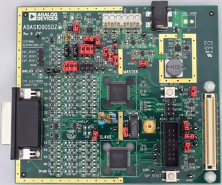
A photograph of the ADAS1000 evaluation board connected to the SDP board is shown in Figure 2.
The evaluation board has been designed to offer 1-lead to 12-lead ECG measurement.

Batteries Used in Portable ECG Applications
The types of batteries used in portable ECG equipment vary, and, in some cases, AA or AAA batteries are found, allowing for easy replacement or recharging.
Batteries contribute to the overall weight of the instrument. Because patient comfort is important, minimizing overall solution size and weight while maintaining battery life is a prime concern in portable ECG applications.
Newer products are likely to use battery chemistries, such as lithium ion, and achieve operating time from a few hours to a number of days, depending on the product.
The battery voltage range depends on the supply range of the components within the system. An AVDD of 3.3 V is required for the ADAS1000. Therefore, if the ADP151regulator is used, the battery must supply at least a 3.7 V minimum, which requires a 400 mV headroom. The nominal cell voltage of a lithium ion or lithium polymer battery is 3.7 V; however, the discharge voltage is about 3.2 V. Therefore, a stack of two is required to guarantee a 3.7 V minimum for the ADP151.
Selecting the Right Power Solution
The ADAS1000 requires a minimum of two power rails, AVDD and IOVDD. As shown in Table 1, the ADCVDD and DVDD rails are optional, and these supplies may be derived from the AVDD or IOVDD rails, respectively, using the on-chip LDOs within the ADAS1000.
| Power Rail | Voltage Range | Function |
| AVDD |
3.3 V ± 5% |
Analog supply rail |
| OVDD |
1.65 V to 3.6 V |
Digital interface supply rail |
| ADCVDD (optional) |
1.8 V ± 5% |
ADC supply rail; can be derived from AVDD using internal LDO |
| DVDD (optional) |
1.8 V ± 5% |
Digital supply rail; can be derived from IOVDD using internal LDO |
On the evaluation board, AVDD and IOVDD are powered with 3.3 V. The 3.3 V was chosen for the IOVDD rail to maintain compatibility with the SPORT interface on the EVAL-SDP-CB1Z. If interfaced to a microcontroller operating at a lower supply voltage, the IOVDD supply voltage can be as low as 1.65 V.
Alternatively, where a more power efficient solution is required, the ADCVDD and DVDD internal rails can be disabled using the hardware pin (VREG_EN) on the ADAS1000, which allows the ADCVDD and DVDD rails to be driven by the external supplies. Because the ADCVDD rail powers the ADCs on the chip, it must be kept as clean as possible, and it must not be shared with noisy digital supplies.
Depending on operational mode, the supply current on the AVDD rail for a single ADAS1000 is typically between 8 mA and 15 mA with all five channels enabled; unused channels can be disabled to lower power.
A dedicated ADP151 is used for both the AVDD and IOVDD supplies on the evaluation board. Note that each ADP151 is capable of driving 200 mA and can therefore supply other components within the system. The input to the ADP151 regulators comes from a 5 V rail generated on the board for other purposes.
A single ADP151 can supply both the AVDD and IOVDD rails if appropriate filtering is added to ensure the AVDD rail is kept free of any digital noise on the IOVDD rail.
The EVAL-ADAS1000SDZ evaluation board has been designed to provide power to the EVAL-SDP-CB1Z board that requires 5 V at approximately 250 mA. The ADP2503 buck boost dc-to-dc converter generates the 5 V rail from an input supply to the board of 4.5 V to 5.5 V.
If this hardware is battery powered with the SDP board connected, the overall power consumption quickly discharges the batteries.
Common Variations
Other pin compatible ECG front ends in the ADAS1000 family offer less functionality. For example, the ADAS1000-4 is a 3-channel version with pace and respiration, the ADAS1000-3 offers three ECG channels without pace or respiration. The ADAS1000-2 is a companion device with five ECG channels that is intended for use in a gang configuration to support a 12-lead ECG measurement (nine ECG electrodes and one RLD). Table 2 shows the differences between the members of the family. The range of products ensures flexible configurations for expansion from small lead counts all the way to 15-lead measurements and beyond.
For higher efficiency, a dc-to-dc converter can be used for the supplies if care is taken with respect to layout and ripple noise.
| Generic | ECG | Operation | Right Leg Drive | Respiration | Pace Detection | Shield Driver | Master Interface1 | Package Option |
| ADAS1000 | Five ECG channels |
Master/slave |
Yes |
Yes |
Yes |
Yes |
Yes |
LFCSP, LQFP |
| ADAS1000-1 | Five ECG channels |
Master/slave |
Yes |
Yes | Yes |
LFCSP |
||
| ADAS1000-2 | Five ECG channels |
Slave |
LFCSP, LQFP |
|||||
| ADAS1000-3 |
Three ECG channels |
Master/slave |
Yes |
Yes | Yes |
LFCSP, LQFP |
||
| ADAS1000-4 | Three ECG channels | Master/slave |
Yes |
Yes |
Yes |
Yes | Yes | LFCSP, LQFP |
| 1 Master interface is provided for users wishing to use their own digital pace algorithm; see the Secondary Serial Interface section of ADAS1000 data sheet. | ||||||||
Circuit Evaluation & Test
Equipment List
The following equipment is needed:
- The EVAL-ADAS1000SDZ kit, which includes the EVALADAS1000SDZ evaluation board, a 5 V wall wart supply, and a CD with the ADAS1000 evaluation software
- The EVAL-SDP-CB1Z System Demonstration Board
- A PC with a USB port and the ADAS1000 evaluation software installed
- A patient simulator or function generator can be used for signal capture
A detailed discussions of the use of the ADAS1000 evaluation board is available in the ADAS1000SDZ User Guide. Figure 3 shows a typical screen capture using the evaluation board software with a patient simulator attached to the evaluation board.

Noise Measurements
The evaluation board software was used to capture the peak-topeak noise performance of the ECG lead path using the ADAS1000 evaluation board. The results are shown in Figure 4.
The device was configured using the following conditions:
- A gain setting of 1.4
- An ADC sample rate 2 MSPS (high performance mode)
- A data rate of 2 kHz
- In digital lead mode (digitally calculated leads)
- ECG channels connected to internal test tone of 1.3 V

The x-axis is time based, showing a capture over a number of seconds, and the y-axis scale is in μV, showing noise performance on the order of ±7 μV for these conditions. This was in line with expectations of the ADAS1000 performance and aligned with performance gathered on the same hardware using a low noise linear bench-top supply. This confirmed that the ADP151 power supply circuit on the evaluation board was not causing a significant increase in the overall noise from the ADAS1000.
Conditions Regarding the Use of This Evaluation Board and Circuit Note
See complete disclaimer in the ADAS1000SDZ User Guide.
This evaluation board design is being provided “as is” without any express or implied representations or warranties of any kind and the use of this board or design shall impose no legal obligation on Analog Devices, Inc., and its subsidiaries, employees, directors, officers, servants and agents. In addition, it is understood and agreed to that the evaluation board or design is not authorized for use in safety critical healthcare applications (such as life support) where malfunction or failure of a product can be expected to result in personal injury or death. This board must not be used for diagnostic purposes and must not be connected to a human being or animal. It must not be used with a defibrillator or other equipment that produces high voltages in excess of the supply rails on the board.
This evaluation board is provided for evaluation and development purposes only. It is not intended for use or as part of an end product. Any use of the evaluation board or design in such applications is at your own risk and you shall fully indemnify Analog Devices, its subsidiaries, employees, directors, officers, servants and agents for all liability and expenses arising from such unauthorized usage. You are solely responsible for compliance with all legal and regulatory requirements connected to such use.