LTC6991
PRODUCTIONTimerBlox: Resettable, Low Frequency Oscillator
- Part Models
- 18
- 1ku List Price
- Starting From $1.72
Part Details
- Period Range: 1ms to 9.5 Hours
- Configured with 1 to 3 Resistors
- <1.5% Maximum Frequency Error
- Output Reset Function
- 2.25V to 5.5V Single Supply Operation
- 55µA to 80µA Supply Current
- (2ms to 9.5hr Clock Period)
- 500µs Start-Up Time
- CMOS Output Driver Sources/Sinks 20mA
- –55°C to 125°C Operating Temperature Range
- Available in Low Profile (1mm) SOT-23 (ThinSOT™) and 2mm × 3mm DFN Packages
- AEC-Q100 Qualified for Automotive Applications
The LTC6991 is a silicon oscillator with a programmable period range of 1.024ms to 9.54 hours (29.1µHz to 977Hz), specifically intended for long duration timing events. The LTC6991 is part of the TimerBlox® family of versatile silicon timing devices.
A single resistor, RSET, programs the LTC6991’s internal master oscillator frequency. The output clock period is determined by this master oscillator and an internal frequency divider, NDIV, programmable to eight settings from 1 to 221.
In normal operation, the LTC6991 oscillates with a 50% duty cycle. A reset function is provided to truncate the pulse (reducing the duty cycle). The reset pin can also be used to prevent the output from oscillating.
The RST and OUT pins can be configured for active-low or active-high operation using a polarity function.
| POL Bit | RST Pin | Output State |
| 0 | 0 | Oscillating |
| 0 | 1 | 0 (reset) |
| 1 | 0 | 1 (reset) |
| 1 | 1 | Oscillating |
Applications
- “Heartbeat” Timers
- Watchdog Timers
- Intervalometers
- Periodic “Wake-Up” Call
- High Vibration, High Acceleration Environments
- Portable and Battery-Powered Equipment
Documentation
Data Sheet 1
Reliability Data 1
User Guide 1
Technical Articles 2
Video 1

Solutions Bulletin & Brochure 1
Product Selector Card 1
ADI has always placed the highest emphasis on delivering products that meet the maximum levels of quality and reliability. We achieve this by incorporating quality and reliability checks in every scope of product and process design, and in the manufacturing process as well. "Zero defects" for shipped products is always our goal. View our quality and reliability program and certifications for more information.
| Part Model | Pin/Package Drawing | Documentation | CAD Symbols, Footprints, and 3D Models |
|---|---|---|---|
| LTC6991CDCB#TRMPBF | 6-Lead DFN (2mm x 3mm w/ EP) | ||
| LTC6991CDCB#TRPBF | 6-Lead DFN (2mm x 3mm w/ EP) | ||
| LTC6991CS6#TRMPBF | 6-Lead TSOT-23 | ||
| LTC6991CS6#TRPBF | 6-Lead TSOT-23 | ||
| LTC6991HDCB#TRMPBF | 6-Lead DFN (2mm x 3mm w/ EP) | ||
| LTC6991HDCB#TRPBF | 6-Lead DFN (2mm x 3mm w/ EP) | ||
| LTC6991HS6#TRMPBF | 6-Lead TSOT-23 | ||
| LTC6991HS6#TRPBF | 6-Lead TSOT-23 | ||
| LTC6991HS6#WTRMPBF | 6-Lead TSOT-23 | ||
| LTC6991HS6#WTRPBF | 6-Lead TSOT-23 | ||
| LTC6991IDCB#TRMPBF | 6-Lead DFN (2mm x 3mm w/ EP) | ||
| LTC6991IDCB#TRPBF | 6-Lead DFN (2mm x 3mm w/ EP) | ||
| LTC6991IS6#TRMPBF | 6-Lead TSOT-23 | ||
| LTC6991IS6#TRPBF | 6-Lead TSOT-23 | ||
| LTC6991IS6#WTRMPBF | 6-Lead TSOT-23 | ||
| LTC6991IS6#WTRPBF | 6-Lead TSOT-23 | ||
| LTC6991MPS6#TRMPBF | 6-Lead TSOT-23 | ||
| LTC6991MPS6#TRPBF | 6-Lead TSOT-23 |
| Part Models | Product Lifecycle | PCN |
|---|---|---|
|
Jun 30, 2020 - 20_0244 Notification of Wafer Fab Location Change for 0.6µm CMOS Process Devices from ADI Milpitas (Hillview) to Vanguard Int. (Taiwan) |
||
| LTC6991CDCB#TRMPBF | PRODUCTION | |
| LTC6991CDCB#TRPBF | PRODUCTION | |
| LTC6991CS6#TRMPBF | PRODUCTION | |
| LTC6991CS6#TRPBF | PRODUCTION | |
| LTC6991HDCB#TRMPBF | PRODUCTION | |
| LTC6991HDCB#TRPBF | PRODUCTION | |
| LTC6991HS6#TRMPBF | PRODUCTION | |
| LTC6991HS6#TRPBF | PRODUCTION | |
| LTC6991HS6#WTRMPBF | PRODUCTION | |
| LTC6991HS6#WTRPBF | PRODUCTION | |
| LTC6991IDCB#TRMPBF | PRODUCTION | |
| LTC6991IDCB#TRPBF | PRODUCTION | |
| LTC6991IS6#TRMPBF | PRODUCTION | |
| LTC6991IS6#TRPBF | PRODUCTION | |
| LTC6991IS6#WTRMPBF | PRODUCTION | |
| LTC6991IS6#WTRPBF | PRODUCTION | |
| LTC6991MPS6#TRMPBF | PRODUCTION | |
| LTC6991MPS6#TRPBF | PRODUCTION | |
This is the most up-to-date revision of the Data Sheet.
Software Resources
Can't find the software or driver you need?
Request a Driver/SoftwareHardware Ecosystem
| Parts | Product Life Cycle | Description |
|---|---|---|
| Analog Temperature Sensors 1 | ||
| LTC2997 | PRODUCTION | Remote/Internal Temperature Sensor |
Tools & Simulations
LTspice 4
- LTC6991 Demo Circuit - Low Frequency Voltage Controlled Oscillator (250Hz to 1kHz)
- LTC6991 Demo Circuit - TimerBlox: Resettable, Low Frequency Oscillator (8 Second to 8.5 Minute)
- LTC6991/LTC6994 Demo Circuit - Intervalometer for Time-Lapse Photography (Adjustable Aperture from 1/4sec to 4sec)
- LTC6991 - Counters, Timers and Delay Linear
Models for the following parts are available in LTspice:
- LTC6991
LTC6991: Low Frequency Oscillator
Open Tool
LTspice® is a powerful, fast and free simulation software, schematic capture and waveform viewer with enhancements and models for improving the simulation of analog circuits.
Evaluation Kits


LTC6991 Demo Board | 1Hz (1s) Fixed Frequency
Resources
Reference Designs


USB-Powered, 2.4 GHz RF Low Noise Amplifier Receiver with Overpower Protection Circuit
Part Used
Design & Integration Tools


USB-Powered, 915 MHz RF Low Noise Amplifier Receiver with Overpower Protection Circuit
Part Used
Design & Integration Tools


USB-Powered, 433.92 MHz RF Low Noise Amplifier Receiver with Overpower Protection
Part Used
Design & Integration Tools


USB Powered 5.8 GHz RF LNA Receiver with Output Power Protection
Part Used
Design & Integration Tools
Videos
-
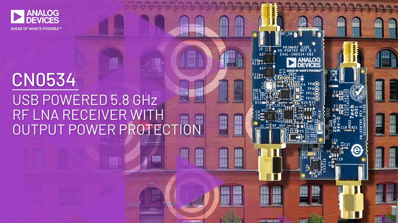 CN0534: USB Powered 5.8 GHz RF LNA w/ Output Power Protection