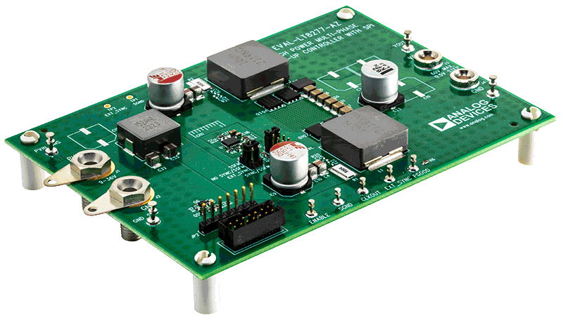
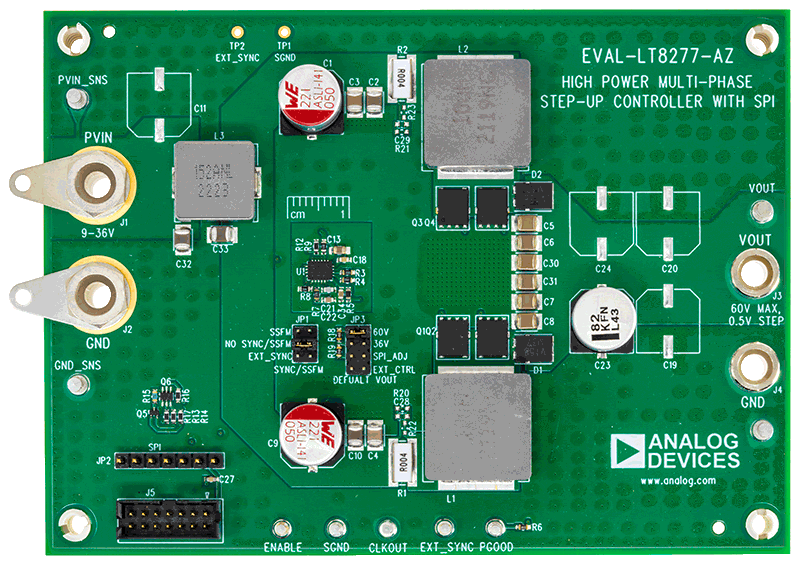
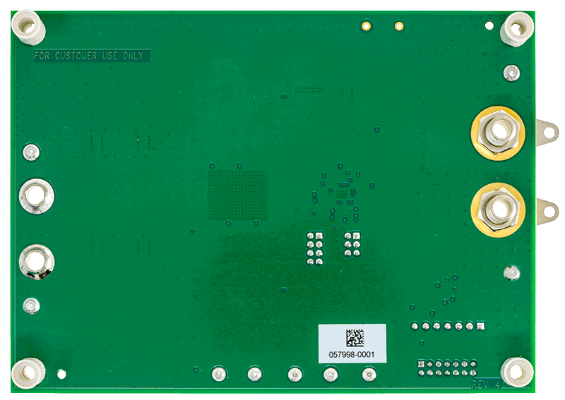
Evaluation circuit EVAL-LT8277-AZ is a dual-phase non-synchronous high-power step-up converter featuring the LT8277. It regulates the output voltage up to 60V and drives up to a 3A load at 60V when the VIN is between 9V and 36V. The EVAL-LT8277-AZ runs at 200kHz switching frequency with the ability to turn on spread spectrum frequency modulation (SSFM) for reduced EMI emission. It can run with or without SPI communications. Multiple EVAL-LT8277-AZ can be paralleled to deliver more output power. A graphic user interface (GUI) is available when connected to a DC2026C Linduino One demo circuit.
The LT8277 is a dual-phase interleaved current mode boost and SEPIC controller. It has a wide input voltage range from 3V to 40V and an adjustable switching frequency between 100kHz and 2MHz. The EVAL-LT8277-AZ enables users to easily evaluate LT8277’s features, like the SPI interface, PGOOD output status reporting, frequency synchronization, clock output for 4- or 8-phase operation, etc. Users could change the RT resistor to set the circuit’s switching frequency, change ENABLE resistors to set the minimum input voltage when the circuit starts operation and change VC pin components to adjust loop compensation.
With SPI control, EVAL-LT8277-AZ can set the output voltage from 9V to 60V in a 0.5V step. The SPI interface also configures on/off of the clock output (CLKOUT pin), clock output phase shift, speed of soft start, and keep/drop phase two at light load conditions. The MODE pin controls the watchdog timer of the SPI interface. The JP3 jumper sets the MODE pin voltage or enables GUI control of the MODE pin. For a detailed way of using the SPI interface and MODE pin, refer to the EVAL-LT8277-AZ GUI manual.
The EVAL-LT8277-AZ features an input EMI filter for low emissions. Inductor current is sensed by sensing resistors, while DCR sensing is available. Power-stage MOSFETs and diodes are optimized to achieve high efficiency. The PCB has large copper planes and extensive vias for excellent high-power thermal performance.
The LT8277 data sheet gives a complete description of the device, operation, and applications information. The data sheet must be read in conjunction with this user guide for EVAL-LT8277-AZ. The LT8277RUDCM#WPBF is assembled in a 3mm x 4mm, Plastic Side-solderable QFN package with a thermally enhanced ground pad. A proper board layout is essential for maximum thermal performance. Refer to the data sheet layout considerations section.
Windows®-based graphical user interface (GUI) software is available for use with the EV kit and can be downloaded from the LT8277 website. Follow the EVAL-LT8277-AZ GUI manual for software installation and evaluation guidance.


