Abstract
This application note discusses the some of the benefits of digital calibration and shows common calibration circuits by application.
Calibration makes products accurate, safe, and affordable. It allows manufacturers to deliver "perfect" devices at competitive prices. Maxim's large variety of digital calibration parts enables quick automated testing and adjustment.
Calibration Circuit Table of Contents
ADC
Amplifier Support
Current Source/Sink
DAC
Filter
LCD Bias
LED
Multiplexer
Power Supplies
Sensor Support
VCO
Voltage Reference
These ideas are presented pictorially to save time and speed comprehension. Most engineers will spend a second or two on each block until one fits their application. They can then click on the diagram to jump to the source application note or datasheet for more information.
Electronic calibration can reduce cost in many areas. It can remove manufacturing tolerances, specify less-expensive components, reduce test time and customer returns, and improve reliability. It also increases customer satisfaction, lowers warranty costs, and speeds product delivery.
Digitally controlled calibration devices and potentiometers (pots) are replacing mechanical pots in many products. By removing human error, these parts reduce test time and expense. Additionally, digital devices are insensitive to vibration, dust, dirt, and moisture, which can cause failure in mechanical pots. The increased reliability can reduce product liability concerns and improve product safety. Furthermore, the small size of electronic calibration devices benefits small board layouts and portable devices.
Calibration Circuits by Application
ADC


See application note 2013, "Voltage Reference Scaling Technique Increases ADC Accuracy to Keep Costs Down."


See application note 4617, "ADC Input Translator."


See application note 647, "Comparator/DAC Combinations Solve Data-Acquisition Problems."
Amplifier Support


See the MAX5389 data sheet.


See application note 184, "Digitally-Controlled Phase Shift Using the DS1669."


See application note 558, "Tech Brief 2: Dual-Polarity Amplifier is Controlled Digitally."


See application note 3846, "Analysis of a Digitally Controlled Wien-Bridge Oscillator."


See application note 4344, "Rail Splitter, from Abraham Lincoln to Virtual Ground."
>

See application note 4348, "Minimize Voltage Offsets in Precision Amplifiers."


See application note 429, "Programmable-Gain Amplifier, Using the MAX532 DAC."
Current Source/Sink


See the MAX6008 data sheet.


See application note 3464, "Precision Current Source is Software-Programmable."


See application note 3748, "How to Create a Precision Current Source Using a DS4303 or DS4305."


See application note 4474, "4.096V, 80mA Precision Reference."


See application note 1010, "Methods of Controlling Laser Drivers: POTs and DACs."
DAC


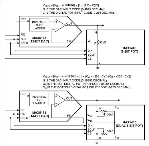
See application note 807, "Force/Sense DAC Applications."


See application note 3990, "Current-Source DAC with PIN Diode Provides RF Attenuation and Thermal Compensation."


See application note 647, "Comparator/DAC Combinations Solve Data-Acquisition Problems."
Filter


See application note 3077, "A Digitally Controllable Lowpass Filter Using a Digital Potentiometer."
LCD Bias


See the MAX5389 data sheet.


See the MAX5436 data sheet.
LED


See application note 4025, "DACs vs. Digital Potentiometers: Which Is Right for My Application?"


See the MAX8595 data sheet.


See application note 1037, "Charge-Pump and Step-Up DC-DC Converter Solutions for Powering White LEDs in Series or Parallel Connections."
Multiplexer


See application note 261, "Calibration-Multiplexers Ease System Calibration."
Power Supplies


See application note 225, "Using Digital Potentiometers in Adjustable Step-Down DC-DC Converter Designs."


See the MAX5389 data sheet.


See application note 226, "Step-Up DC-DC Converter Calibration and Adjustment Using a Digital Potentiometer."


See application note 818, "Digital Adjustment of DC-DC Converter Output Voltage in Portable Applications."


See application note 3657, "Ultra-Low-Noise LDO Achieves 6nV/√Hz Noise Performance."


See the DS4422 data sheet.


See application note 4101, "Differentiating Digital Potentiometer Features."


See application note 818, "Digital Adjustment of DC-DC Converter Output Voltage in Portable Applications."
Sensor Support


See application note 3426, "Resistive Bridge Basics: Part One."


See application note 4022, "MAX1452 Nonlinearity-Correction Application Circuit."


See application note 807, "Force/Sense DAC Applications."
VCO


See application note 2095, "External Resistor Minimizes Digipot Loading."


See application note 3846, "Analysis of a Digitally Controlled Wien-Bridge Oscillator."
Voltage Reference


See application note 430, "Voltage Reference Compensates Reference Junction."


See application note 3531, "How to Reduce Reference Noise by Half."


See application note 4290, "Ratiometric Design Overcomes the 25% Tolerance of a Digital Potentiometer."


See application note 4494, "Methods for Calibrating Gain Error in Data-Converter Systems."


See the MAX5389 data sheet.


See application note 3657, "Ultra-Low-Noise LDO Achieves 6nV/√Hz Noise Performance."
Related to this Article
Products
1µA SOT23 Precision Shunt Voltage Reference
High-Precision Voltage References with Temperature Sensor
32-Tap, One-Time Programmable, Linear-Taper Digital Potentiometers
Low-Voltage, Single 8 to 1 and Dual 4 to 1 Cal Multiplexers
Two-/Four-Channel, I²C, 7-Bit Sink/Source Current DAC
32-Channel, 16-Bit, Voltage-Output DACs with Serial Interface
32-Channel, 14-Bit, Voltage-Output DACs with Serial Interface
Low-Cost, Low-Power, 8-Bit DACs with 2-Wire Serial Interface in SOT23
Buffered, Fast-Settling, Octal, 12/10/8-Bit, Voltage-Output DACs
12-Bit DACs with 32-Channel Sample-and-Hold Outputs
10-Bit, Nonvolatile, Linear-Taper Digital Potentiometers
Triple NV Low Step Size Variable Resistor Plus Memory
Temperature-Controlled, NV, I²C, Logarithmic Resistor
Hex Nonvolatile Potentiometer with I/O and Memory
±15V, 128-Tap, Low-Drift Digital Potentiometers
Dual NV Audio Taper Digital Potentiometer
{{modalTitle}}
{{modalDescription}}
{{dropdownTitle}}
- {{defaultSelectedText}} {{#each projectNames}}
- {{name}} {{/each}} {{#if newProjectText}}
-
{{newProjectText}}
{{/if}}
{{newProjectTitle}}
{{projectNameErrorText}}


