CN0172


Overview
Design Resources
Design & Integration File
- Schematic
- Bill of Materials
- Gerber Files
- PADS Files
- Assembly Drawing
Evaluation Hardware
Part Numbers with "Z" indicate RoHS Compliance. Boards checked are needed to evaluate this circuit.
- EVAL-CN0172-SDPZ ($171.20) High Accuracy Multichannel Thermocouple Measurement Solution
- EVAL-SDP-CB1Z ($116.52) Eval Control Board
Device Drivers
Software such as C code and/or FPGA code, used to communicate with component's digital interface.
AD779x Linux GitHub Driver Source Code
AD7793 - Microcontroller No-OS Driver
Features & Benefits
- 3 channel K-type thermocouple measurement system
- Typical temperature range of -200 C to +1200 C
- Highly accurate temperature measurement to 0.25 degrees
- 16-bit digital temperature sensor used for cold junction compensation
Product Categories
Markets and Technologies
Parts Used
Documentation & Resources
-
CN0172 Software User Guide10/18/2018WIKI
-
ADT7320/ADT7420: Digital Temperature Sensors FAQ5/10/2011PDF657 kB
-
MT-101: Decoupling Techniques2/14/2015PDF954 kB
-
MT-023: ADC Architectures IV: Sigma-Delta ADC Advanced Concepts and Applications2/14/2015PDF936 kB
-
MT-022: ADC Architectures III: Sigma-Delta ADC Basics2/14/2015PDF289 kB
-
MT-031: Grounding Data Converters and Solving the Mystery of "AGND" and "DGND"3/20/2009PDF144 kB
-
MT-004: The Good, the Bad, and the Ugly Aspects of ADC Input Noise - Is No Noise Good Noise?3/4/2009PDF342 kB
-
CN-0172: High Accuracy Multichannel Thermocouple Measurement Solution3/22/2013PDF319 kB
Circuit Function & Benefits
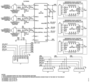
The function of the circuit shown in Figure 1 is to provide a high accuracy multichannel thermocouple measurement solution. Achieving a precision thermocouple measurement requires a signal chain of precision components that amplifies the small thermocouple voltage, reduces noise, corrects nonlinearity, and provides accurate reference junction compensation (commonly referred to as cold junction compensation). This circuit addresses all these challenges for measuring thermocouple temperature with better than ±0.25°C accuracy.
The circuit shown in Figure 1 shows how three K type thermocouples are connected to the AD7793 precision 24-bit sigma-delta (Σ-Δ) analog-to-digital converter (ADC) to measure the thermocouple voltage. Because the thermocouple is a differential device rather than an absolute temperature measurement device, the reference junction temperature must be known to get an accurate absolute temperature reading. This process is known as reference junction compensation, commonly referred to as cold junction compensation. In this circuit, the ADT7320 precision 16-bit digital temperature sensor is used for the cold junction reference measurement and provides the required accuracy.
This type of application is popular where a cost-effective, accurate temperature measurement is required over the wide temperature ranges offered by thermocouples.

Circuit Description
The circuit in Figure 1 is designed to measure the temperature of three K type thermocouples at the same time using the ADT7320, a ±0.25°C accurate, 16-bit digital SPI temperature sensor.
Thermocouple Voltage Measurement
The interface between the thermocouple and the AD7793 ADC is a thermocouple connector and filter. Each connector (J1, J2, and J3) connects directly to a set of differential ADC inputs. The filter on the inputs to the AD7793 reduces any noise pickup in the thermocouple leads before the signal reaches the AIN(+) and AIN(−) inputs of the ADC. The AD7793 has an on-chip multiplexer, buffer, and instrumentation amplifier to amplify the small voltage from the thermocouple measurement junction.
Cold Junction Measurement
The ADT7320 precision 16-bit digital temperature sensor is used to measure the reference (cold) junction temperature with an accuracy of ±0.25°C over the −20°C to +105°C temperature range. The ADT7320 is fully calibrated at the factory, and no user calibration is required. The ADT7320 contains an internal band gap reference, a temperature sensor, and a 16-bit Σ-Δ ADC to measure and digitize the temperature to 0.0078°C resolution.
Both the AD7793 and ADT7320 are controlled by an SPI interface using the System Demonstration Platform (EVAL-SDP-CB1Z). Both AD7793 and ADT7320 can also be controlled by a micro-controller.

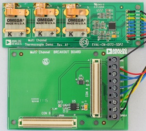
Figure 2 shows the EVAL-CN0172-SDPZ circuit evaluation board with three K type thermocouple connectors, the AD7793 ADC, and the ADT7320 temperature sensor mounted on a separate flexible printed circuit board (PCB) between two copper contacts for the reference temperature measurement.
Figure 3 shows a side view of the ADT7320 mounted on a separate flexible PCB and inserted between the two copper contacts of the thermocouple connector. The flexible PCB shown in Figure 3 has advantages over small FR4-type PCBs because it is thinner and more flexible. This allows the ADT7320 to be mounted neatly in between the copper contacts of the thermocouple connector to minimize temperature gradients between the reference junction and ADT7320.

The small size and thinness of the flexible PCB also allows the ADT7320 to quickly respond to temperature changes at the reference junction. Figure 4 shows the typical thermal response time of the ADT7320.

This solution is flexible and allows other types of thermocouples to be used, such as J type or T type thermocouples. The K type was selected for this circuit note because of its popularity. The actual thermocouple chosen has an exposed tip. The measurement junction is outside the probe wall and is exposed to the target medium.
The advantages of the exposed tip are that it provides the best heat transfer, has the quickest response time, and is low cost and light weight. The disadvantages of the exposed tip are that it is susceptible to mechanical damage and corrosion. As a result, it is not suitable for harsh environments. However in cases where quick response time is needed, the exposed tip is the best choice. If an exposed tip is required in an industrial environment, electrical isolation may be required in the signal chain. This can be addressed by using digital isolators (see www.analog.com/iCoupler).
Unlike a traditional thermistor or resistance temperature detector (RTD), the ADT7320 is a fully plug-and-play solution that does not require multipoint calibration after board assembly or consume processor and memory resources with calibration coefficients and linearization routines. The ADT7320 avoids self-heating issues that undermine the accuracy of traditional resistive sensor solutions because it only dissipates 700 μW (typical) of power at 3.3 V.
Guidelines for Accurate Temperature Measurement
The following guidelines ensure that the ADT7320 accurately measures the temperature of the reference junction.
Power Supply: If the ADT7320 is powered from a switching regulator, noise generated above 50 kHz may affect the temperature accuracy specification. To prevent this, use an RC filter between the power supply and VDD. Carefully choose the value of components used to ensure that the peak value of the supply noise is less than 1 mV.
Decoupling: The ADT7320 must have a decoupling capacitor mounted as close as possible to VDD to ensure accurate temperature measurement. A decoupling capacitor, such as a 0.1 μF high frequency ceramic type is recommended. In addition, use a low frequency decoupling capacitor in parallel with the high frequency ceramic, such as a 10 μF to 50 μF tantalum capacitor.
Maximizing Thermal Conduction: The primary thermal path from the reference junction to the ADT7320 is through the plastic package and the backside exposed paddle (GND). Because the copper contacts are connected to the ADC inputs, the backside paddle cannot be connected in this application because it affects the biasing to the ADC inputs.
Guidelines for Accurate Voltage Measurement
The following guidelines ensure that the AD7793 accurately measures the voltage at the thermocouple measurement junction.
Decoupling: The AD7793 must have decoupling capacitors mounted as close as possible to both AVDD and DVDD to ensure accurate voltage measurement. Decouple AVDD with a 10 μF tantalum capacitor in parallel with a 0.1 μF ceramic capacitor to GND. In addition, decouple DVDD with a 10 μF tantalum capacitor in parallel with a 0.1 μF ceramic capacitor to GND. Refer to Tutorial MT-031 and Tutorial MT-101 for more discussion on grounding, layout techniques, and decoupling techniques.
Filtering: The differential inputs of the AD7793 act to remove most of the common-mode noise on the thermocouple lines. Differential low-pass filters comprising R1, R2, and C3, for example, placed at the front end of the AD7793 reduce noise pickup that can be present in the thermocouple leads. The C1 and C2 capacitors provide additional common-mode filtering. Because the AIN(+) and AIN(−) analog inputs to the ADC are differential, most of the voltages in the analog modulator are common-mode voltages. The excellent common-mode rejection (100 dB minimum) of the AD7793 further removes common-mode noise on these inputs.
Other Challenges Resolved with this Solution
The following summarizes how other challenges mentioned earlier with thermocouples are resolved with this solution.
Thermocouple Voltage Amplification: The output voltage of the thermocouple changes by only a few μV per degree. In this case, the popular K type thermocouple changes 41 μV/°C. This small signal requires a large gain stage before the ADC conversion. The AD7793 internal programmable gain amplifier (PGA) provides a gain up to 128. For this solution, a gain of 16 was used to allow the AD7793 to run its own internal full-scale calibration using its internal reference.
Correction for Thermocouple Nonlinearity: The AD7793 provides excellent linearity across a wide temperature range (−40°C to +105°C), requiring no correction or calibration by the user. To determine the actual thermocouple temperature, the reference temperature measurement is first converted into an equivalent thermoelectric voltage using equations provided by the National Institute of Standards and Technology (NIST). This voltage is added to the thermocouple voltage measured by the AD7793, and the summation is then translated back into a thermocouple temperature, again using NIST equations. An alternative approach involves using look-up tables. However, to get the same accuracy, the size of the lookup table could be substantial which would require additional memory resources from the host controller. All the processing is done in the software using the EVAL-SDP-CB1Z.
Complete schematics and layouts for the EVAL-CN0172-SDPZ can be found in the CN-0172 Design Support Package: www.analog.com/CN0172-DesignSupport.
Common Variations
For applications that require less accuracy and precision, the AD7792 16-bit Σ-Δ ADC can be used instead of the AD7793 24-bit Σ-Δ ADC. For the reference temperature measurement, the ±0.5°C accurate ADT7310 digital temperature sensor can be used instead of the ±0.25°C accurate ADT7320. Both the AD7792 and ADT7310 are available with an SPI interface.
Circuit Evaluation & Test
The system described uses the EVAL-CN0172-SDPZ and the EVAL-SDP-CB1Z. The CN0172 Breakout Board is included with the EVAL-CN0172-SDPZ board.
Equipment Needed
The following equipment is needed:
- An Oil bath
- The EVAL-CN0172-SDPZ circuit evaluation board
- The CN0172 Breakout Board (Included with the EVAL-CN0172-SDPZ board)
- The EVAL-SDP-CB1Z circuit evaluation board
- The CN0172 evaluation board software
- A Datron 4808 calibrator
- A Hart Scientific 1590 super thermometer
- A Hart Scientific precision probe
- GPIB cables (3)
- A PC and Windows XP or later running LabVIEW with a GPIB card and an USB 2.0 port
Setup and Test
The test setup shown in Figure 5 was used to evaluate the performance of the multichannel thermocouple solution. A Datron calibrator was used to provide a precise voltage source for the three thermocouple inputs. The temperature of the oil baths was measured with the super thermometer and controlled via the GPIB bus.
LabVIEW software for the CN0172 controls the EVAL-CN0172-SDPZ via the USB port, the EVAL-SDP-CB1Z, Breakout Board, and the SPI bus. The power for the EVAL-SDP-CB1Z is obtained from the USB bus, and the 3.3 V output of the EVAL-SDP-CB1Z supplies power for the EVAL-CN0172-SDPZ.
If oil bath measurements are not required, the EVAL-CN0172-SDPZ can be used to measure the three thermocouple temperatures by using the USB interface with a PC and the software provided on the CD.
Information and details regarding test setup and calibration, and how to use the evaluation software for data capture can be found in the CN0172 User Guide found at: www.analog.com/CN0172-UserGuide.

Test Results
Figure 6 shows a plot of the thermocouple solution error over various thermocouple temperatures using various fixed values of cold junction (CJ) temperatures. Total solution error ≤ ±0.25°C is achieved over a wide temperature range. Note that the accuracy of the solution can be further improved by performing a system calibration of the AD7793 ADC.

Figure 7 shows a plot of the thermocouple solution error over various CJ temperatures using various fixed values of thermocouple temperatures. Total solution error ≤ ±0.25°C is achieved over a wide temperature range.