MAX2871

PRODUCTION

23.5MHz to 6000MHz Fractional/Integer-N Synthesizer/VCO

High-Performance, Wide-Frequency PLL with Integrated VCOs Simplifies Signal Chain and Improves Performance

Part Models
2
1ku List Price
Starting From $7.29
Viewing:

Part Details

  • Output Binary Buffers/Dividers Enable Extended Frequency Range
    • Divider Ratios of 1/2/4/8/16/32/64/128
    • 23.5MHz to 6000MHz
  • High-Performance Phase Frequency Detector (PFD) and Reference Frequency Reduces Spectral Noise
    • PFD Up to 140MHz
    • Reference Frequency Up to 210MHz
  • Low Normalized Inband Phase Noise of -230dBc/Hz Reduces System Noise Floor Contribution
  • Manual or Automatic VCO Selection Permits Fast Switching
  • Output Phase Reset and Adjustment Allow Synchronization of Multiple Synthesizers
  • On-Chip Temperature Sensor with 7-Bit ADC Ensures Optimum VCO Selection
  • Cycle Slip Reduction and Fast Lock Features Improve Accuracy and Acquisition Time
  • VCO Lock Maintained Over Entire Temperature Range Provides Glitch-Free Operation
  • Dual Differential Programmable Outputs Maximize Flexibility of Use
MAX2871
23.5MHz to 6000MHz Fractional/Integer-N Synthesizer/VCO
MAX2871: Functional Diagram
Add to myAnalog

Add product to the Products section of myAnalog (to receive notifications), to an existing project or to a new project.

Create New Project
Ask a Question

Documentation

Learn More
Add to myAnalog

Add product to the Products section of myAnalog (to receive notifications), to an existing project or to a new project.

Create New Project

Hardware Ecosystem

Parts Product Life Cycle Description
Phase Locked Loop with Integrated VCO 1
MAX2870 PRODUCTION 23.5MHz to 6000MHz Fractional/Integer-N Synthesizer/VCO
Modal heading
Add to myAnalog

Add product to the Products section of myAnalog (to receive notifications), to an existing project or to a new project.

Create New Project

Tools & Simulations


Evaluation Kits

MAX2871EVKIT

Evaluation Kit for the MAX2870 and MAX2871

Features and Benefits

  • Easy Evaluation of the MAX2870 and MAX2871
  • 50Ω SMA Connectors
  • All Critical Peripheral Components Included
  • PC Control Software
  • Proven PCB Layout
  • Fully Assembled and Tested

Product Details

The MAX2870/MAX2871 evaluation kits (EV kits) simplify the testing and evaluation of the MAX2870 and MAX2871 ultra-wideband phase-locked loop (PLL) with integrated voltage-control oscillators (VCOs). Each EV kit is fully assembled and tested at the factory. Standard 50Ω SMA connectors are included on the EV kits for the inputs and outputs to enable quick and easy evaluation on the test bench.

This document provides a Quick Start guide, a description of the EV kit circuit, a Troubleshooting Guide, the circuit schematic, a list of components for the EV kit, and diagrams for each layer of the PCB.

Note: This EV kit data sheet supports the MAX2870 (Rev B) and MAX2871 EV kits. Customers using MAX2870 (Rev A) EV kit can access the schematic, PCB layout, and user guide under the Help menu of the EV kit software.

Applications

  • Clock Generation
  • PMAR/LMAR/Public Safety Radio
  • Satellite Communications
  • Test and Measurement
  • Wireless Infrastructure
  • Wireless LANs/CATV

MAX2870EVKIT

Evaluation Kit for the MAX2870 and MAX2871

Features and Benefits

  • Easy Evaluation of the MAX2870 and MAX2871
  • 50Ω SMA Connectors
  • All Critical Peripheral Components Included
  • PC Control Software
  • Proven PCB Layout
  • Fully Assembled and Tested

Product Details

The MAX2870/MAX2871 evaluation kits (EV kits) simplify the testing and evaluation of the MAX2870 and MAX2871 ultra-wideband phase-locked loop (PLL) with integrated voltage-control oscillators (VCOs). Each EV kit is fully assembled and tested at the factory. Standard 50Ω SMA connectors are included on the EV kits for the inputs and outputs to enable quick and easy evaluation on the test bench.

This document provides a Quick Start guide, a description of the EV kit circuit, a Troubleshooting Guide, the circuit schematic, a list of components for the EV kit, and diagrams for each layer of the PCB.

Note: This EV kit data sheet supports the MAX2870 (Rev B) and MAX2871 EV kits. Customers using MAX2870 (Rev A) EV kit can access the schematic, PCB layout, and user guide under the Help menu of the EV kit software.

Applications

  • Clock Generation
  • PMAR/LMAR/Public Safety Radio
  • Satellite Communications
  • Test and Measurement
  • Wireless Infrastructure
  • Wireless LANs/CATV

MAX2871EVKIT
Evaluation Kit for the MAX2870 and MAX2871
MAX2870EVKIT
Evaluation Kit for the MAX2870 and MAX2871

Reference Designs

MAXREFDES161
MAXREFDES161 Circuits from the lab

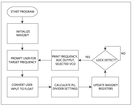
Frequency Synthesizer Shield with the MAX2871

Features and Benefits

  • MAX2871 Fractional/Integer-N Synthesizer/VCO
  • +3.3V and +5V compatible logic
  • SMA output connectors
  • On-board 50.0MHz crystal oscillator
  • Mbed® library
  • Arduino shield form factor
MAXREFDES161
Frequency Synthesizer Shield with the MAX2871
MAXREFDES161
MAXREFDES161
MAXREFDES161 Block Diagram
MAXREFDES161 Firmware

Latest Discussions

Recently Viewed