LT8292

RECOMMENDED FOR NEW DESIGNS

60V Low IQ Full-Featured Synchronous Buck-Boost Controller

Part Models
4
1ku List Price
Starting From $3.49

Part Details

  • 4-Switch Single Inductor Architecture that Allows VIN Above, Below, or Equal to VOUT 
  • Proprietary Buck-Boost Peak Current Mode
  • Low Ripple Burst Mode: 30μA IQ 
  • Forced Continuous Mode or Pulse-Skipping Operation
  • Split Gate Driver Outputs
  • Selectable Dead Time Settings
  • Leaderless Current Sharing
  • Adjustable and Phase-lockable: 100kHz to 650kHz
  • Spread Spectrum Frequency Modulation
  • ±2% Output Voltage Accuracy: 1V ≤ VOUT ≤ 60V
  • ±5% Input or Output Average Current Accuracy
  • Integrated Bootstrap Diodes 
  • VOUT Disconnected from VIN During Shutdown
  • 38-Lead Thin Shrink Small Outline Package (TSSOP) with Exposed Pad
  • Automotive Qualified
LT8292
60V Low IQ Full-Featured Synchronous Buck-Boost Controller
Ask a Question

Documentation

Learn More

Software Resources

Can't find the software or driver you need?

Request a Driver/Software

Tools & Simulations

LTspice 2


LTpowerCAD

Design tools for the following parts are available in LTpowerCAD:

  • LT8292
LTspice

LTspice® is a powerful, fast and free simulation software, schematic capture and waveform viewer with enhancements and models for improving the simulation of analog circuits.


Evaluation Kits

eval board
EVAL-LT8292-BZ

60V Synchronous Buck-Boost Controller

Product Details

The evaluation circuit EVAL-LT8292-BZ features the LT®8292: a parallelable 4-switch synchronous buck-boost controller. The LT8292 regulates the output voltage and output or input current from an input voltage below, equal to, or above the output voltage. With a wide 5.5V to 60V input range and a seamless transition between operating regions, the LT8292 is ideal for automotive, industrial, and telecom systems. The buck-boost peak current mode architecture allows adjustable phase-lockable 100kHz to 650kHz fixed frequency operation or internal spread spectrum operation for low electromagnetic interference (EMI). Additionally, the LT8292 features ISHARE and IGND pins, allowing for multi-IC leaderless current-sharing capabilities for higher-power applications.

The EVAL-LT8292-BZ operates from a 9V to 36V input voltage range and generates an output of 12V. A maximum output current of 25A allows up to 300W power delivery while achieving efficiencies that exceed 97%. The switching frequency is set to 100kHz to achieve high power and efficiency. The board can also be modified to support larger MOSFETs for higher power.

The output voltage and EN/UVLO are both programmed by resistor dividers. The LT8292 supports an output voltage range from 1V to 60V with a 2% tolerance. EN/UVLO is set so the circuit will turn off when the input voltage falls below 8.1V and will turn on when the input voltage rises above 8.5V. The LT8292 utilizes split pull-up/pull-down gate drivers and four selectable dead time settings. The EVAL-LT8292-BZ allows for simple alterations to optimize these features.The PGOOD status flag indicates when the output voltage is within ±8% of the final regulation voltage.

The EVAL-LT8292-BZ features MOSFETs that complement the 5V gate drive of the LT8292 to achieve high efficiency. 40V MOSFETs are used on the input and output sides of the four-switch topology. Ceramic capacitors are used at both the circuit input and output because of their small size and high ripple current capability. In addition to ceramic capacitors, there are bulk aluminum polymer capacitors on the input and output to make input and output stable during the transient period. The ICTRL input is pulled up to the VREF pin through a 100kΩ resistor to set the output current limit to its maximum, and an external voltage on the ICTRL pin can be used to lower the current limit. A capacitor at the SS pin programs soft-start.

High power operation, parallel capability, 5.5V input voltage operation, 4-switch buck-boost topology, proprietary peak current mode architecture, fault protection, and output current limiting make the LT8292 attractive for high power voltage regulator circuits.

The LT8292AFE is available in a thermally enhanced 38-lead TSSOP package. The LT8292 data sheet gives a complete description of this part, its operation, and applications information. The LT8292 data sheet must be read in conjunction with this user guide to properly use the evaluation circuit EVAL-LT8292-BZ. The evaluation circuit is designed to be easily reconfigured to suit other applications. Consult the factory for assistance.

Design files for this circuit board are available.

eval board
EVAL-LT8292-AZ

60V Dual-Phase Synchronous Buck-Boost Controller

Product Details

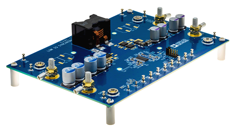
Evaluation circuit EVAL-LT8292-AZ features the LT®8292: a parallelable 4-switch synchronous buck-boost controller. The LT8292 regulates the output voltage and output or input current from an input voltage below, equal to, or above the output voltage. With a wide 5.5V to 60V input range and a seamless transition between operating regions, the LT8292 is ideal for automotive, industrial, and telecom systems. The buck-boost peak current mode architecture allows adjustable phase-lockable 100kHz to 650kHz fixed frequency operation or internal spread spectrum operation for low Electromagnetic interference (EMI). Additionally, LT8292 features ISHARE and IGND pins, allowing for multi-IC leaderless current-sharing capabilities for higher-power applications.

The EVAL-LT8292-AZ operates from 9V to 36V input voltage range and generates an output of 12V. A maximum output current of 50A allows up to 600W power delivery while achieving efficiencies that exceed 97%. The board utilizes two LT8292s in parallel, both set to 100kHz, to achieve high power and efficiency.

The output voltage and EN/UVLO are both programmed by resistor dividers. The LT8292 supports an output voltage range from 1V to 60V with a 2% tolerance. EN/UVLO is set so the circuit will turn off when the input voltage falls below 8.1V and will turn on when the input voltage rises above 8.5V.

LT8292 utilizes split pull-up/pull-down gate drivers and four selectable dead time settings. EVAL-LT8292-AZ allows for simple alterations to optimize these features.

The PGOOD status flag indicates when the output voltage is within ±8% of the final regulation voltage.

The EVAL-LT8292-AZ features MOSFETs that comple-ment the 5V gate drive of the LT8392 to achieve high efficiency. 40V MOSFETs are used on the input and output side of the four-switch topology. Ceramic capacitors are used at both the circuit input and output because of their small size and high ripple current capability. In addition to ceramic capacitors, there are bulk aluminum polymer capacitors on the input and output to make input and output stable during the transient period.

The ICTRL input is pulled up to the VREF pin through a 100kΩ resistor to set the output current limit to its maximum, and an external voltage on the ICTRL pin can be used to lower the current limit. A capacitor at the SS pin programs soft-start.

High power operation, parallel capability, 5.5V input voltage operation, 4-switch buck-boost topology, proprietary peak current mode architecture, fault protection, and output current limiting make the LT8292 attractive for high power voltage regulator circuits.

The LT8292AFE is available in a thermally enhanced 38-lead TSSOP package. The LT8292 datasheet gives a complete description of this part, its operation, and applications information. The LT8292 data sheet must be read in conjunction with this user guide to properly use the evaluation circuit EVAL-LT8292-AZ. The evaluation circuit is designed to be easily reconfigured to suit other applications, including the example schematics in the datasheet. Consult the factory for assistance.

EVAL-LT8292-BZ
60V Synchronous Buck-Boost Controller
EVAL-LT8292-AZ
60V Dual-Phase Synchronous Buck-Boost Controller

Latest Discussions

Recently Viewed