MAXQ2000
PRODUCTIONLow-Power LCD Microcontroller
Industry's Highest MIPS/mA, 16-Bit, RISC Microcontroller
- Part Models
- 2
- 1ku List Price
- price unavailable
Part Details
- High-Performance, Low-Power, 16-Bit RISC Core
- DC to 20MHz Operation, Approaching 1MIPS per MHz
- Dual 1.8V Core/3V I/O Enables Low Power/Flexible Interfacing
- 33 Instructions, Most Single Cycle
- Three Independent Data Pointers Accelerate Data Movement with Automatic Increment/Decrement
- 16-Level Hardware Stack
- 16-Bit Instruction Word, 16-Bit Data Bus
- 16 x 16-Bit, General-Purpose Working Registers
- Optimized for C-Compiler (High-Speed/Density Code)
- Program and Data Memory
- 32kWords Flash Memory, Mask ROM for High-Volume Applications
- 10,000 Flash Write/Erase Cycles
- 1kWord of Internal Data RAM
- JTAG/Serial Boot Loader for Programming
- Peripheral Features
- Up to 50 General-Purpose I/O Pins
- 100/132 Segment LCD Driver
- Up to 4 COM and 36 Segments
- Static, 1/2, and 1/3 LCD Bias Supported
- No External Resistors Required
- SPI™ and 1-Wire® (-RAX/RAX+/-RFX/-RFX+ Only) Hardware I/O Ports
- One or Two Serial UARTs
- One-Cycle, 16 x 16 Hardware Multiply/Accumulate with 48-Bit Accumulator
- Three 16-Bit Programmable Timers/Counters
- 8-Bit, Subsecond, System Timer/Alarm
- 32-Bit, Binary Real-Time Clock with Time-of-Day Alarm
- Programmable Watchdog Timer
- Flexible Programming Interface
- Bootloader Simplifies Programming
- In-System Programming Through JTAG
- Supports In-Application Programming of Flash Memory
- Ultra-Low-Power Consumption
- 190µA typ at 8MHz Flash Operation, PMM1 at 2.2V
- 700nA typ in Lowest Power Stop Mode
- Low-Power 32kHz Mode and Divide-by-256 Mode
The MAXQ2000 microcontroller is a low-power, 16-bit device that incorporates a liquid-crystal display (LCD) interface that can drive up to 100 (-RBX/-RBX+) or 132 (-RAX/-RAX+/-RFX/-RFX+) segments. The MAXQ2000 is uniquely suited for the blood-glucose monitoring market, but can be used in any application that requires high performance and low-power operation. The device can operate at a maximum of either 14MHz (VDD > 1.8V) or 20MHz (VDD > 2.25V). The MAXQ2000 has 32kWords of flash memory, 1kWord of RAM, three 16-bit timers, and one or two universal synchronous/asynchronous receiver/transmitters (UARTs). Flash memory aids prototyping and low-volume production. The microcontroller core is powered by a 1.8V supply, with a separate I/O supply for optimum flexibility. An ultra-low-power sleep mode makes these parts ideal for battery-powered, portable equipment.
Note: Designers must have the following documents to fully use all the features of this device. This data sheet contains pin descriptions, feature overviews, and electrical specifications. Errata sheets contain deviations from published specifications. The user's guides offer detailed information about device features and operation.
- MAXQ2000 IC data sheet
- MAXQ2000 revision-specific errata sheet (Click here for availability)
- MAXQ Family User's Guide
- MAXQ Family User's Guide: MAXQ2000 Supplement
Applications
- Battery-Powered and Portable Devices
- Consumer Electronics
- Data-Acquisition Systems and Data Loggers
- Electrochemical and Optical Sensors
- Gas and Chemical Sensors
- Home Appliances
- HVAC
- Industrial Control
- Medical Instrumentation
- Security Sensors
- Smart Transmitters
- Thermostats/Humidity Sensors
Documentation
Data Sheet 1
Reliability Data 1
User Guide 8
Application Note 13
Design Note 12
Technical Articles 33
ADI has always placed the highest emphasis on delivering products that meet the maximum levels of quality and reliability. We achieve this by incorporating quality and reliability checks in every scope of product and process design, and in the manufacturing process as well. "Zero defects" for shipped products is always our goal. View our quality and reliability program and certifications for more information.
| Part Model | Pin/Package Drawing | Documentation | CAD Symbols, Footprints, and 3D Models |
|---|---|---|---|
| MAXQ2000-RAX+ | 68-LFCSP-10X10X0.85 | ||
| MAXQ2000-RBX+ | 56-TQFN-8X8X0.75 |
| Part Models | Product Lifecycle | PCN |
|---|---|---|
|
Oct 25, 2016 - 1622 ASSEMBLY |
||
| MAXQ2000-RAX+ | PRODUCTION | |
This is the most up-to-date revision of the Data Sheet.
Evaluation Kits
Evaluates: SPI and SMBus/I²C-Compatible Parts
Resources
Evaluation Kit for the MAXQ2000/MAX98357A/MAX98357B/MAX98358 and MAX98371
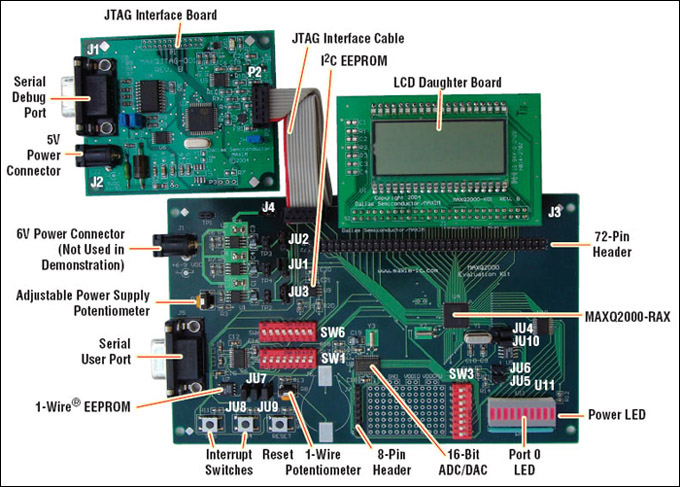
Evaluation Kit for the MAXQ2000
Resources
Evaluation Kit for the MAXQ2010
Latest Discussions
No discussions on maxq2000 yet. Have something to say?
Start a Discussion on EngineerZone®