ADIN1110
推荐用于新设计可靠的工业低功耗 10BASE-T1L 以太网 MAC-PHY
- 产品模型
- 4
产品详情
- 符合10BASE-T1L IEEE 802.3cg-2019标准要求
- 电缆延伸范围高达1700 m,支持1.0 V/2.4 V
- 集成SPI的MAC
- 支持OPEN Alliance 10BASE-T1x MAC-PHY串行接口
- 16个MAC地址过滤器
- 带28 kB缓冲器的高低优先级队列
- 直通或存储转发操作
- 支持IEEE 1588时间戳
- 统计计数器
- 低功耗:42 mW(双电源,1.0 V p-p)
- 诊断
- 具有TDR的电缆故障检测
- 具有MSE的链路质量指示器
- 帧生成器和检查器
- 多种环回模式
- IEEE测试模式支持
- 支持1.0 V p-p和2.4 V p-p发送电平
- 4针MDI(RXN、RXP、TXN和TXP)
- 适合本质安全应用
- 外部端接电阻
- 自动协商
- 25 MHz晶振或外部时钟输入
- 电磁兼容性(EMC)测试标准
- IEC 61000-4-4电快速瞬变(±4 kV)
- IEC 61000-4-2 ESD(±4 kV接触放电)
- IEC 61000-4-2 ESD(±8 kV空气放电)
- IEC 61000-4-6传导抗扰度(10 V/m)
- IEC 61000-4-5浪涌(±4 kV)
- IEC 61000-4-3辐射抗扰度(A类)
- EN55032辐射发射(B类)
- 小型封装:40引脚(6 mm × 6 mm) LFCSP封装
- 温度范围
- 工业:−40°C至+85°C
- 扩展范围:−40°C至+105°C
ADIN1110是一款面向工业以太网应用的超低功耗单端口10BASE-T1L收发器,符合IEEE® 802.3cg-2019™以太网标准,支持长程10 Mb/s单对以太网(SPE)应用。ADIN1110具有集成的媒体访问控制(MAC)接口,可通过4线式串行外设接口(SPI)与各种主机控制器直接连接。该SPI可使用低功耗处理器,无需集成MAC,整体系统级功耗非常低。SPI可以配置为使用OPEN联盟SPI协议或通用SPI协议。
ADIN1110支持可编程发射电平、外部端接电阻和独立的接收和发送引脚,适合各种本质安全应用。
ADIN1110集成电压电源监控和上电复位(POR)电路,可提高系统级鲁棒性。
ADIN1110采用40引脚、6 mm × 6 mm引脚架构芯片级封装(LFCSP)。
应用
- 现场仪器仪表
- 楼宇自动化和消防安全
- 工厂自动化
- 边缘传感器和执行器
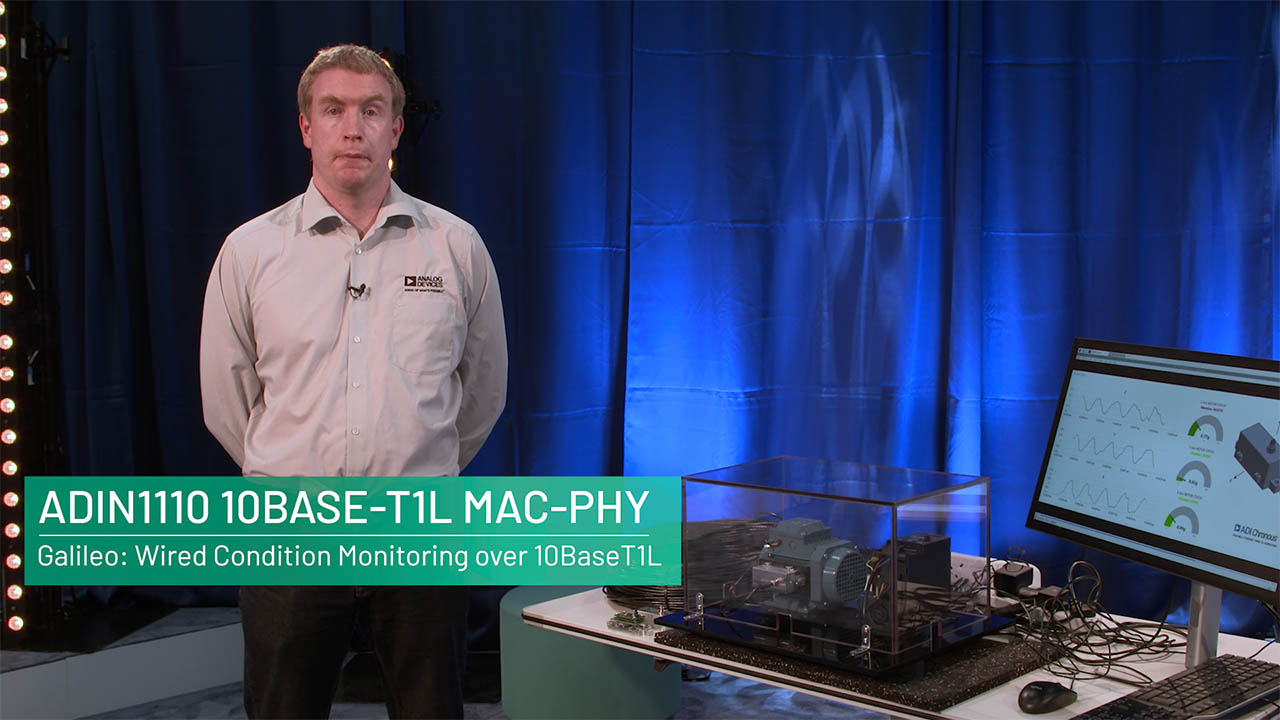
- 状态监控和机器连接
想要开始开发 10BASE-T1L 解决方案吗?
请使用 不妨给我们的专家团队发送电子邮件,以获取 ADIN1110 或评估板的样品。
参考资料
数据手册 1
用户手册 1
应用笔记 1
技术文章 8
视频 7


解决方案设计及宣传手册 1
器件驱动器 6
模拟对话 1
非常见问题 1
思想领导力 4
ADI 始终高度重视提供符合最高质量和可靠性水平的产品。我们通过将质量和可靠性检查纳入产品和工艺设计的各个范围以及制造过程来实现这一目标。出货产品的“零缺陷”始终是我们的目标。查看我们的质量和可靠性计划和认证以了解更多信息。
| 产品型号 | 引脚/封装图-中文版 | 文档 | CAD 符号,脚注和 3D模型 |
|---|---|---|---|
| ADIN1110BCPZ | 40-Lead LFCSP (6mm x 6mm x 0.75mm) | ||
| ADIN1110BCPZ-R7 | 40-Lead LFCSP (6mm x 6mm x 0.75mm) | ||
| ADIN1110CCPZ | 40-Lead LFCSP (6mm x 6mm x 0.75mm) | ||
| ADIN1110CCPZ-R7 | 40-Lead LFCSP (6mm x 6mm x 0.75mm) |
这是最新版本的数据手册
软件资源
器件驱动器 5
Evaluation Software 0
找不到您所需的软件或驱动?
工具及仿真模型
IBIS 模型 1
评估套件


Arduino Form-factor Development Platform Based on MAX32690 ARM Cortex-M4 Microcontroller
资料
软件


Software-configurable Analog and Digital I/O with 10BASE-T1L Evaluation and Development Platform
资料
软件


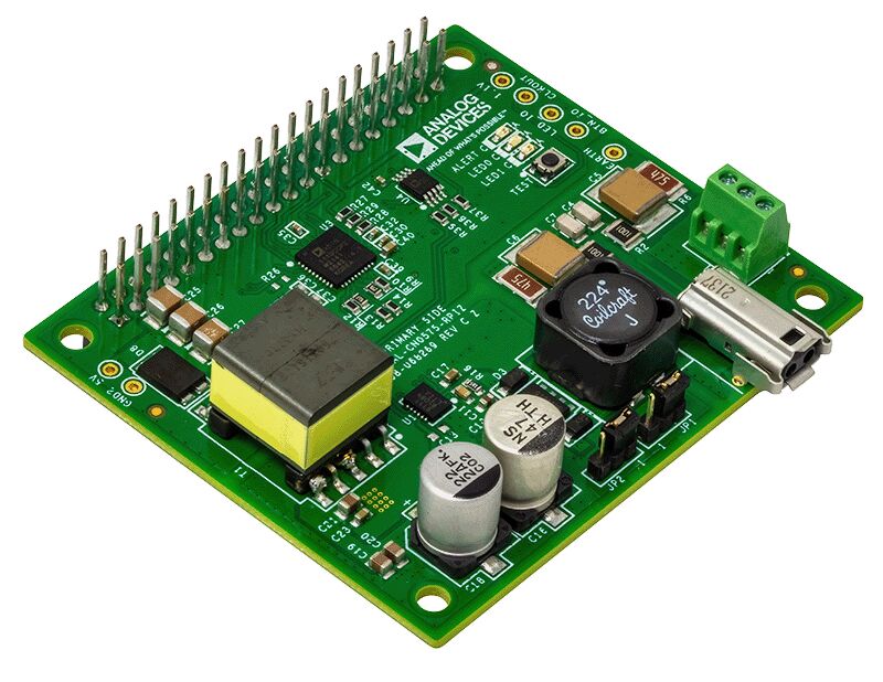
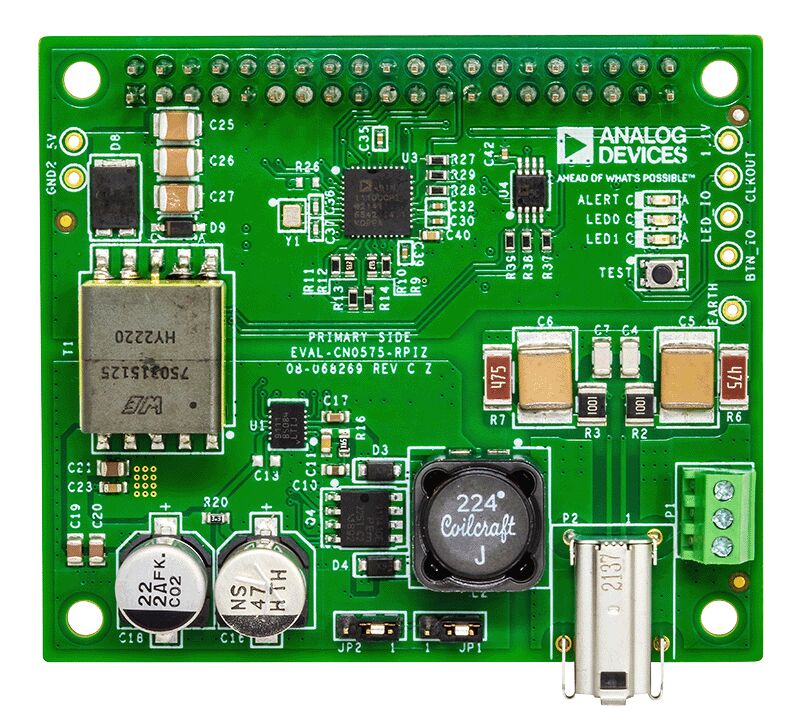
评估 ADIN1110 稳健、工业、低功耗 10BASE-T1L 以太网 MAC-PHY
资料
软件
参考电路
10BASE-T1L Field Device Development Platform with Class 12 and 13 SPoE
使用部分
设计和集成工具
最新评论
需要发起讨论吗? 没有关于 ADIN1110的相关讨论?是否需要发起讨论?
在EngineerZone®上发起讨论