Design Note 51: Gain Trimming In Instrumentation Amplifier Based Systems
Gain trimming is almost always required in instrumentation amplifier based systems. Gain uncertainties, most notable in transducers, necessitate such a trim.
Figure 1, a conceptual system, shows several points as candidates for the trim. In practice, only one of these must actually be used. The appropriate trim location varies with the individual application.

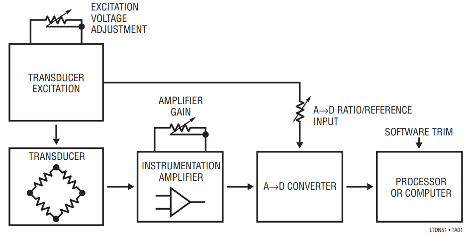
Figure 1. Conceptual Transducer Signal Conditioning Path Showing Gain Trimming Possibilities. In Practice, Only One Adjustment Is Required.
Figure 2 approaches gain trimming by altering transducer excitation. The gain trim adjustment results in changes in the LT1010’s output. The LT1027 reference and LT1097 ensure output stability. Transducer output varies with excitation, making this a viable approach. It is important to consider that gain “lost” by reducing transducer drive translates into reduced signal-to-noise ratio. As such, gain reduction by this method is usually limited to small trims, e.g., 5-10%. Similarly, too much gain introduced by this method can cause excessive transducer drive, degrading accuracy. The transducer manufacturer’s data sheet should list the maximum permissible drive for rated accuracy.

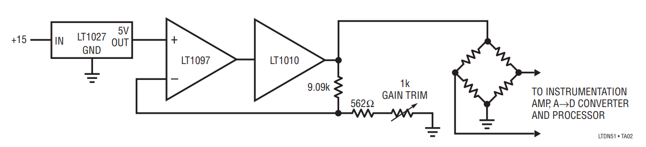
Figure 2. Gain Trimming by Adjustment of Transducer Excitation. This Method is Useable for Small (5 to 10%) Trims. Large Trims Will Cause Excessive Transducer Power Dissipation or Starved Outputs.
Figure 3 adjusts gain in the instrumentation amplifier stage. The fixed gain LT1101 instrumentation amplifier feeds a second amplifier where the trim occurs. As both cases show, the gain trim may be up or down. A secondary benefit of this trim scheme is that it permits optional offset summing and filtering. Note that either the inverter or follower may be set up for gain addition or reduction. The sole limitation is the signal polarity reversal imposed by the inverter case. This may be corrected by reversing the instrumentation amplifiers’ inputs.

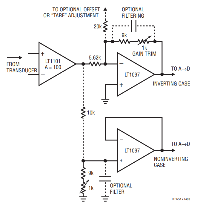
Figure 3. Gain Trimming at the Instrumentation Amplifier. A Second Stage Permits Trimming Gain Up or Down, and Allows Filtering and Offsets to Be Summed In.
A final hardware based gain trim is shown in Figure 4. Here, the A→D reference input is scaled to the appropriate voltage by the op amp and associated components. The op amp input is usually the transducer excitation voltage or, in cases where this is not possible, a reference.

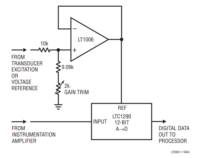
Figure 4. Gain Trimming By Adjustment of the A→D Reference Input Voltage.
One final way to trim gain is in software. If a processor is involved in the system this is a viable alternative. The software trim does a simple code conversion on the A→D output. When using this approach utilize as much of the analog components’ dynamic range as possible to avoid signal-to-noise degradation.

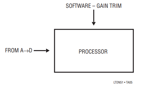
Figure 5. Software Based Trimming.
著者
