概要
モーション・コントロールのアプリケーションの中には、非常に高い精度が求められるものがあります。そうしたアプリケーションでは、滑らかな動きと高い分解能での位置決めを実現しなければなりません。そのために不可欠な要素がステッピング・モーター(ステッパ・モーター)です。ただ、求められる要件を満たすためには、ステッピング・モーターに適用する制御方式が重要になります。特に、フルステッピング制御、ハーフステッピング制御、マイクロステッピング制御の違いを把握しておくことが肝要です。本稿では、まずマイクロステッピング制御の基本を押さえた上で、フルステッピング、ハーフステッピングとの違いを明らかにします。また、マイクロステッピング制御を利用するために最適な製品群などを紹介します。
はじめに
ステッピング・モーターを使用する場合、比較的シンプルな制御方式によって高い精度を得ることができます。そのため、産業分野や医療分野のアプリケーションなどで広く利用されています。例えば、3DプリンタやCNC工作機械(Computer Numerical Control Machine)など、3軸の位置決めを必要とするシステムが代表的な用途です。ACモーターやブラシレスDCモーターでも、高い精度は得られます。ただ、ステッピング・モーターには、精度が高いだけではなく、オープンループ制御による動作が可能で、低速でも高いトルクが得られるという長所があります。また、多くのステッピング・モーターは費用対効果が高いものだと言えます。しかも、サーボ・モーターほど複雑ではありません。更に、ブラシ付きDCモーターとは異なり、ステッピング・モーターでは大きなトルクによって位置を保持することができます。
本稿で取り上げるマイクロステッピングは、ステッピング・モーターで使用される非常に有用な制御方式です。これを利用すれば、モーターをより小刻みに(より細かいステップで)動かすことができます。つまり、1回転当たりの離散的な位置の数を大幅に増やすことが可能です。その結果、モーターからの騒音や振動を大幅に低減できるようになります。なお、アナログ・デバイセズは、モーション・コントロール用の製品群として「ADI Trinamic」を提供しています。ADI Trinamicには、ステッピング・モーター用のドライバICや、ボード・レベルのモジュール、最大256のマイクロステップでステッピング・モーターを駆動するための完全なソリューションが含まれています。
ステッピング・モーターの基本
まずは、ステッピング・モーターに関する基本的な事柄について説明します。
モーターの構造
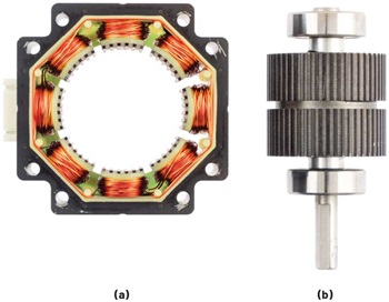
ステッピング・モーターは、磁石をベースとするロータとコイルをベースとするステータで構成されます。図1に示したのは、ハイブリッド2相ステッピング・モーターの例です。この種のモーターでは、2つの磁石カップを備えるロータを使用します。通常、各磁石カップには50個の歯が付いています。また、これらの磁石は逆の極性を示し、物理的には互いにオフセットされています。ステータは、中央のロータを囲むよう複数の位置に配置された2つのワイヤ製コイルで構成されます。各相に順に通電することにより、モーターが回転します。

動作
ステッピング・モーターの動作は、離散的なものになります。つまり、1回転に相当する角度(360°)を等間隔のステップに分割し、そのステップを単位として回転します。例えば、1回転当たり200の離散的な位置を備えるステッピング・モーターの場合、そのステップ角は1.8°となります。ステップ角は、以下の式(1)に示すように、360°をフルステップの数で割ることによって求められます。

図2に示すように、モーターのコイルに電流を流すと、永久磁石をベースとするロータを引き寄せたり反発したりする磁界が生じます。この磁界に応じてロータが回転します。モーターを回転させ続けるためには、各コイルに交互に通電し、磁界がロータの前方にある状態を維持する必要があります。


ステッピング動作の詳細
ここからは、ステッピング・モーターのステッピング動作について詳しく説明していきます。それに向けて、図3に示した2相ステッピング・モーターのモデルを例にとることにします。このモデルは1つの磁極対を備えていますが、全体としては簡略化されたものになっています。


フルステッピング制御
フルステッピング制御では、ドライバによって2つのコイルに正または負の電流を流します。両方の相が同時に通電するので、最大のトルクが得られます。モーターのシャフトは、コイルに流す電流の向きを切り替えることによって回転します。切り替えのパターンは、多くの場合、転流(commutation)と呼ばれ、通常は図4に示すような周期的なシーケンスに従います。この制御方式では、以下の4つの状態が存在することになります。


フルステッピング制御を採用すれば、高精度のステップ、正確な速度制御、高い保持トルク(holding torque)を実現できます。また、フルステッピングでは、モーターの高速動作時に最大のトルク出力を得ることが可能です。しかし、フルステッピング制御では、図5に示すような問題が起きる可能性があります。つまり、モーターの動作に伴って過剰な振動や大きな騒音が発生するかもしれないのです。この振動と騒音は、主にモーターが目標の位置からオーバーシュートしてしまうことが原因で生じます。このオーバーシュートはポジション・ジャンプ(position jump)と呼ばれています。振動や騒音が生じた結果、特定の速度で大きな共振が発生し、それに伴ってトルクが低下します。


単一の磁極対を備えるシンプルなモーターでは、フルステップの転流を使用することで、1回転当たり4つの離散的な位置を得ることができます。これを50の磁極対を備えるモーターに拡張すると、1回転当たりのフルステップ数は200になります(以下参照)。

このような構成により、ロータの歯とコイルの磁界が揃ったときにモーターを特定の位置に向けることが可能になります。
ハーフステッピング制御
ステップのサイズを小さくすれば、位置のオーバーシュート、振動、騒音の問題を改善できます。では、ステップのサイズを小さくするにはどうすればよいのでしょうか。これは、新たな電流の状態を導入することによって実現できます(図6)。ハーフステッピング制御のモデルでは、ロータの位置の数を1磁極対当たり8つに増やします。それにより、位置の分解能が2倍になります。ハーフステップの動作は、モーター用のドライバによって、1相励磁と2相励磁を交互に実行することで実現できます。上記のとおり、ハーフステッピング制御では、振動を抑えつつ位置の分解能を高められます。低速における回転トルクはわずかに増大しますが、新たなハーフステップの位置における保持トルクは低下します。その低下したトルクは、一般に増分トルク(incremental torque)と呼ばれています。


上記のような改善が得られるものの、ハーフステッピング制御には問題がないというわけではありません。同制御を適用したとしても、依然として比較的大きなポジション・ジャンプが生じてしまうからです。これは、モーターの回転が完全に滑らかに行われるわけではないということを意味します。この問題は、特に低速な動作において顕著になります。その結果、求められるようになったのが、マイクロステッピング制御という技術です。
マイクロステップ
マイクロステッピング制御とは何か?
マイクロステッピングは、上述した課題を解決する制御方式です。この方式では、各フルステップを等間隔のマイクロステップに分割します。そして、ステッピング・モーターがマイクロステップを単位として動作するようにします。つまり、フルステップの間の複数の中間位置まで回転できるように制御するということです。そのためには、図7のような構成を使用します。通常、この方式は、低速動作時により高い位置分解能とより滑らかな回転を得るために使用されます。マイクロステップの分解能を高めると(より細かく分割すると)、モーターの移動距離が短くなります。その結果、位置のオーバーシュートとリンギングが低減され、振動と騒音が改善されます。


マイクロステッピング制御の仕組み
図8に示すように、マイクロステッピング制御はモーターに正弦波形の電流を供給することによって実現します。モーター用のドライバは、電流のレギュレーションを利用し、各モーター・コイルに対して正弦波形の電流を正確に供給します。とはいえ、完全な正弦波を生成するのは不可能です。正弦波の質、つまりマイクロステッピング制御の質は、ステッピング・モーター用のドライバが備えるA/Dコンバータ(ADC)とD/Aコンバータ(DAC)の分解能によって制限されます。ADI Trinamicに含まれる各ステッピング・モーター用ドライバは、分解能が最小でも8ビットのADCとDACを搭載しています。そのため、1フルステップに対して最大256のマイクロステップを設定することが可能です。通常、ハイブリッド型のステッピング・モーターでは1回転当たりのフルステップの数が200です。したがって、256マイクロステップの制御を適用すると、1回転当たり最大5万1200の離散的な位置を実現できます。その結果、0.00703125°という極めて高いステップ分解能が得られます。
考慮すべき重要な事柄 - 位置精度と増分トルク
マイクロステッピングを採用すれば、多くのメリットが得られます。しかし、この制御方式にも重要な課題が存在します。課題になるのは、位置精度と増分トルクの2つです。
位置精度とは、モーターの実際の位置と指示された位置との差分(誤差)のことを指します。マイクロステッピング制御では、離散的な位置が増えるため位置分解能が向上します。しかし、位置精度も向上するわけではありません。他の制御方式を使用する場合と変わらず、モーターの精度は構造の公差、モーターの負荷、ドライバがモーターのコイルに所望の電流レベルを正確に供給する能力によって左右されます。これらの要因は、フルステッピングかマイクロステッピングかにかかわらず、モーターの精度に影響を及ぼすということです。
増分トルクは、モーターが停止しているときに、モーターをその位置から引き離すために必要なトルクの大きさとして定義されます。フルステッピングを使用する場合、磁石をベースとするロータはモーターのコイルに対してぴったりと揃っています。その場合、モーターの仕様として規定された保持トルクに等しい最大保持トルクが生成されます。それに対し、マイクロステッピングを使用する場合には、モーターが保持されているマイクロステップの位置に応じて増分トルクが低下します。
増分トルクの大きさは以下に示す式によって近似できます。

ここで、各変数の意味は以下のとおりです。
- TINC:N・mを単位とする増分トルク
- THOLD:N・mを単位とするフルステップの保持トルク
- SDR:ステップ分割比または式(5)を約分した分数の分母
上記のSDRの説明にある式(5)は以下のようなものです。

増分トルクについては、いくつかの具体的な例を見ていただくほうがわかりやすいでしょう。例として、256のマイクロステップを使用するモーターがハーフステップの位置で停止しているケースを考えます。つまり、式(5)については以下のようになります。

SDRの値は、約分した分数の分母の値です。つまり、この例では2になります。この場合、以下に示すように、増分トルクはモーターの保持トルクの70.709%に低下します。

もう1つの例として、モーターが7/256マイクロステップの位置で停止しているケースを考えます。その場合、以下の式が成り立ちます。

この場合のSDRは256です。そのため、以下に示すように、増分トルクはモーターの保持トルクの0.61%まで低下します。

表1に、SDRと増分トルクの関係をまとめました。
| SDR | TINC / THOLD |
| 1 | 100.00% |
| 2 | 70.709% |
| 4 | 38.267% |
| 8 | 17.508% |
| 16 | 9.801% |
| 32 | 4.907% |
| 64 | 2.454% |
| 128 | 1.227% |
| 256 | 0.614% |
増分トルクは、各マイクロステップの位置でモーターを保持するために利用できるトルクを低下させます。ただ、回転トルクはほとんどその影響を受けないという点が重要です。つまり、モーターが回転している間、増分トルクの低下の影響は顕在化しません。実用的な観点から言えば、高い保持トルクが必要な場合には、モーターがフルステップまたはハーフステップの位置で停止するように制御する必要があります。
マイクロステッピングを適用すべきアプリケーション
ステッピング・モーターを使用する多くのアプリケーションは、制御方式としてマイクロステッピングを採用することでメリットを享受しています。例えば、3Dプリンタで高品質のプリントを行うためには、位置分解能を高めつつ振動を最小限に抑える必要があります。また、医療用イメージング機器や手術用のロボットでは、患者にとっての快適さと安全性を確保しなければなりません。そのためには、静かな動作と正確な位置決めを実現する必要があります。マイクロステッピングは、こうした要件を満たすために最適な技術です。
マイクロステッピングでは、ステップのサイズが小さくなるので、位置のオーバーシュートが大幅に低減されます。それにより、振動の減少、効率の向上、より滑らかな動きといった多くのメリットが得られます。特に、機械的な振動が発生するとエネルギーが無駄に消費されます。CNC対応のフライス盤のような一部のアプリケーションでは、振動によって摩耗が進んで信頼性が低下します。マイクロステッピングを採用すれば、機械的な振動や騒音を低減できます。その結果、モーター制御システムの動作に関連する無駄なコストやエネルギーが削減されます。
マイクロステッピングは、上述した以外のアプリケーションでも利用されています。例えば、医療分野で使われる研究用の機器や、バルブ制御システム、エア・ポンプ、CCTV(Closed-circuit Television)、ロボット、ファクトリ・オートメーション(FA)機器などが挙げられます。
ADI Trinamicが提供する製品/技術
ADI Trinamicのソリューションにはステッピング・モーター製品が含まれています。それらの製品は、マイクロステッピング制御の実装に役立つ様々な機能を提供します。ADI Trinamicのすべてのステッピング・モーター製品は、最大256マイクロステップに対応する制御機能を標準機能として搭載しています。
また、ADI Trinamicの中には、MicroPlyer™技術を採用したデバイスも存在します。MicroPlyerは、マイクロステップを利用するための補間技術(インターポレータ)です。同技術を使用すれば、既存のアプリケーションにおいても、分解能の高いマイクロステップを簡単に利用できるようになります。
更に、ADI Trinamicの製品群には、効率が高くフットプリントが小さい完全なソリューションも含まれています。それらのデバイスを採用すれば、スペースと性能に関するあらゆる要件に対応できます。また、ステッピング・モーターを使用するアプリケーションの複雑さが軽減されます。そのため、製品/アプリケーションを市場に投入するまでの時間を短縮することが可能になります。
MicroPlyer - マイクロステップ向けの補間技術
256マイクロステップという分解能は、一部のメーカーが提供するステッパ用ドライバの能力を超えている可能性があります。ADI TrinamicのMicroPlyerは、この問題を解消する技術です。同技術を利用すれば、ステップ分解能の低いシステムを256マイクロステップのシステムにアップグレードすることができます。その際、モーション・コントロール用のロジックを変更する必要はありません。
MicroPlyerは、位置と速度を維持したまま、ステップ・パルス間に追加の電流ステップを組み込む形で機能します。このユニットは、前のステップ期間の時間間隔を測定し、その時間を等しく分割することにより、ステップ・パルス間の時間を補間します。それにより、モーターの駆動に使用される256マイクロステップの内部信号(STEP信号)が生成されます。その結果、分解能の低いステップ信号が入力されている場合でも、256マイクロステップの滑らかな出力が得られます。
ADI Trinamicのステッピング・モーター用ドライバは、既存のアプリケーションに対するドロップイン置換に最適なソリューションです。例えば、16マイクロステップのドライバとシステムをアップグレードし、256マイクロステップのより滑らかな動きを実現したいというニーズがあったとします。モーターのステップ角が1.8°で所望の速度が10回転/秒(RPS)であるとすると、16マイクロステップを使用する場合の入力STEP信号は32kHzに設定する必要があります。通常、256マイクロステップに対応する200フルステップのモーターの場合、10RPSの回転を実現するためには512kHzの信号周波数が必要になります。この周波数は、一部のホスト・コントローラやマイクロコントローラにとっては高すぎる可能性があります。MicroPlyerをサポートするADI Trinamicのドライバを使用すれば、このようなケースに対応できます。そのドライバをドロップインすれば、STEP信号の周波数は32kHzのままで構わないからです。ADI Trinamicのドライバは、STEP信号の補間処理を行います。図9に示すように、256マイクロステップを使用して動きを生成します。


ステッピング・モーター用のスマートなドライバとコントローラ
アナログ・デバイスは、ステッピング・モーター用のスマートなドライバICとして「TMC2240」を提供しています。最大電圧は36V、出力電流は2Armsで、S/D(Step/Direction)インターフェースとSPI(Serial Peripheral Interface)をサポートしています。一方、「TMC5240」はステッピング・モーター用のスマートなドライバ/コントローラICです。この製品も最大電圧は36V、出力電流は2Armsです。TMC2240とTMC5240は、2相ステッピング・モーターをターゲットとした製品です。256マイクロステップに対応するステッピング・モーター用の高度なドライバとして機能します。シリアル通信インターフェースとしては、SPIとUART(Universal Asynchronous Receiver/Transmitter)をサポートしています。また、多様な診断機能や、MicroPlyer技術によるマイクロステップの補間機能を備えています。更に、インデクサ(indexer)機能や、完全に統合された2つのHブリッジ(最大電圧は36V、最大電流は3.0A)、電力散逸の生じない電流検出(ICS)機能も統合されています。TMC2240とTMC5240は、クラス最高レベルのモーション・コントロール機能と電流制御機能を提供します。ADI Trinamicならではの完全な機能セットを採用しているので、滑らかで静かなステッピング・モーターの動作を実現可能です。例えば、CoolStep™は電力効率を向上するために使用されています。また、StallGuard2™/StallGuard4™によって、センサーを使用することなく、負荷とストールを検出できるようになっています。加えて、StealthChop2は静音動作を実現し、SpreadCycle™はリップルを低減する形で電流制御を実現します。更に、SpreadCycleとStealthChop2で実現されるチョッパ動作により、SpreadCycleとStealthChop2を自動的に切り替え、広範な速度にわたって騒音を最小限に抑えることが可能になっています。StealthChop2のチョッパ動作は、ADI Trinamicの洗練された機能です。これを使用することにより、最大の効率と最高のモーター・トルクを両立しつつ騒音のない動作を実現することができます。TMC5240はcDriver™技術を適用したICであり、モーション・コントローラ機能も統合されています。そのため、一般的なモーター用ドライバを使用する場合と比べて、システムのアーキテクチャが簡素化されます。同ICが内蔵する8点モーション・ランプ機能を使えば、所望の位置と動きのプロファイルをプログラムすることも可能です。それにより、ジャークを最小限に抑えられるだけでなく、必要な計算をホスト・コントローラからオフロードすることもできます。
これらの製品は、短絡保護や過電流保護の機能、サーマル・シャットダウン機能、低電圧ロックアウト(UVLO)機能といった診断機能/保護機能を備えています。サーマル・シャットダウンやUVLOが発生した場合、各ドライバICはディスエーブルの状態に移行して損傷の発生を防ぎます。また、これらのICは、1つの外部アナログ入力による測定、ドライバの温度の評価、モーターの温度の推定を行う機能も内蔵しています。
TMC2240とTMC5240は、集積度が高く、エネルギー効率に優れ、フォーム・ファクタが小さい製品です。そのため、これらの製品を採用すれば、サイズが小さく拡張性の高いシステムを構築できます。つまり、費用対効果の高いソリューションを実現可能だということです。例えば、電流検出機能を内蔵しているので、かさばる外付けの電流センス抵抗は不要です。また、両ICは完全なソリューションなので、クラス最高レベルの性能が得られるだけでなく、それぞれのICを使いこなすために必要な学習時間を最小限に抑えられます。
TMC2240/TMC5240は、医療用機器、研究用機器、FA機器、CCTV、セキュリティ機器、3Dプリンタなどのアプリケーションに最適な製品です。
バイポーラ型のステッピング・モーターに最適な高電圧対応のドライバとモーション・コントローラ
「TMC2160」はバイポーラ型のステッピング・モーターに最適な高電圧対応のドライバICです。一方、「TMC5160」には、TMC2160と同様のドライバ機能に加え、モーション・コントローラ機能も統合されています。両ICは、出力の大きい2相ステッピング・モーターの駆動に用いるドライバ機能を提供します。シリアル通信インターフェースとしてはS/D、SPI、UARTをサポートしています。また、256マイクロステップの分解能を備えると共に、MicroPlyerによるマイクロステップの補間機能も提供します。これらのICでは、CoolStep、StealthChop2、StallGuard2、SpreadCycleといったADI Trinamicの技術を利用することで、ドライバの性能が最適化されています。TMC5160はcDriver ICであり、SixPoint™ランプ機能を使用するモーション・コントローラも内蔵しています。このICを採用すれば、位置決めの高速化を図ると共に、台形ランプによって生じる共振を軽減することが可能になります。
両ICはパワーFETを内蔵していません。パワーFETは、大電流や高電圧の仕様に応じて柔軟に選択することになります。高い汎用性が得られるので、バッテリ駆動のシステムから高電圧の産業用システムまで、広範なアプリケーションに対応できます。
TMC2160とTMC5160は、CCTVやセキュリティ機器、FA機器に最適な製品です。医療、繊維、ロボット、産業といった分野で使用するモーター・ドライブにも適用できます。
2相ステッピング・モーターに最適な低電圧対応のドライバIC
「TMC2300」は、低電圧に対応するステッピング・モーター用ドライバICです。バッテリ駆動の2相ステッピング・モーターをターゲットとして設計されています。256マイクロステップの分解能に対応するだけでなく、CoolStep、StealthChop2、StallGuard4、SpreadCycleをベースとする機能も提供します。StealthChop2を利用すれば、携帯用、家庭用、オフィス用のアプリケーションに適した静音性に優れるモーション・コントロールを実現できます。TMC2300では、S/Dインターフェースを利用することで、最大256のマイクロステップを実現可能です。高度な構成を行いたい場合に向けて、オプションでUARTのインターフェースも提供されています。出力段の効率が高く、スタンバイ電流がわずか0.03μAに抑えられているので、長いバッテリ寿命を保証できます。このドライバと共に、2個の単3電池または1個のリチウム・イオン・バッテリを使用した場合、通常はバッテリの電圧が2.0Vまで下がっても動作を継続させられます。
TMC2300は3mm×3mmの小型パッケージを採用しています。1.2Armsの電流を供給できるので、IoT(Internet of Things)機器、ハンドヘルド機器、バッテリ駆動の機器、モバイル型の医療用機器に最適です。
まとめ
マイクロステッピング制御は、多様なステッピング・モーターのアプリケーションに対して数多くのメリットを提供します。特に、効率が高く、位置決めが正確で、騒音を最小限に抑えることが重要なアプリケーションについては、ADI Trinamic製品が適しています。それらの製品が提供するマイクロステッピング制御を適用すれば、非常に大きな効果が得られます。ADI Trinamicのステッピング・モーター用製品は、すべて256マイクロステップに対応する機能を搭載しています。しかも、既存のシステムにそれらの製品を適用することで、マイクロステッピング制御に対応するよう簡単にアップグレードを図ることも可能です。
参考資料
1 George Beauchemin「Microstepping Myths(マイクロステッピングの神話)」Machine Design 75、No. 19、 2003年10月
※初出典 2025年 TECH+(マイナビニュース)
