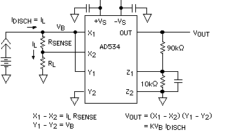
When a battery is life-tested with a prescribed load, its terminal voltage may be a poor indicator of how much of its energy has been discharged. Figure 1 is a circuit of a wattmeter that uses an analog multiplier to measure the actual power (volts × amperes) being delivered by the battery at a given instant. To measure the total energy that has been delivered, the output voltage of the multiplier can either be integrated, using an analog integrator circuit with a very long time constant; or it can be sampled at frequent intervals by an A/D converter, with the Wh readings accumulated in a computer. Both discharge power and total energy can be displayed vs. time over the life of the battery.

In the example of Figure 1, using an AD534 multiplier, with impedance differential inputs, the total load on the battery is RL + RSENSE. The voltage drop across RSENSE, applied to the X input, measures the current through load RL. The battery voltage, VB, is applied to the Y input.The AD534's output is proportional to the battery's true instantaneous output power. Note that RL could be an arbitrary linear or nonlinear grounded load circuit.
Controlled-Power Discharge Circuit
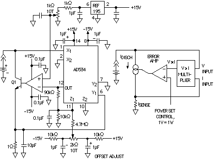
If you desire to measure the battery's terminal performance as it is being discharged at constant power, a power-measuring circuit like Figure 1 can be used in a feedback loop to enforce the constant power constraint. Figure 2 shows a circuit for discharging a battery at a controlled power level. The inset shows the basic scheme, in which the voltage output from the multiplier, representing power, (1 V corresponds to 1 W) is compared with a setpoint, and manipulates the discharge current to maintain power constant at the preset level.
Q1 should be selected to have the appropriate power-dissipation capability; a Darlington transistor could be used for higher power, but be sure to allow for Vsat of the Darlington. The error amplifier should have enough output current to drive the base of the pass transistor (an OP50 might be a good choice for high-current applications).

Bypassing the Regulator at Dropout
One reason for using a voltage regulator is to maintain a constant voltage across the load at a level substantially less than a fresh, fully charged battery's terminal voltage, in order to minimize power dissipation in the load. As the battery is used, its output voltage gradually drops to a level where the regulator is no longer needed for voltage reduction. In fact, most regulators stop functioning when the voltage difference between the battery and load is reduced below a specified "dropout" level. Below this level, the regulator's output drops off sharply, effectively ending the usefulness of the circuit (even though the battery might still have sufficient capacity to feed the load by itself for a somewhat longer period).
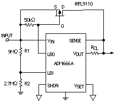
To prevent this from happening, the battery voltage is monitored and a low-battery warning signal is issued, indicating the dis-approaching end of battery life (and of regulator dropout). The circuit of Figure 3, using a regulator with low-battery warning capability, bypasses the regulator when low battery level is detected high-and connects the battery directly to the load circuit.
At high battery levels, the output voltage is regulated and the low battery indicator is off; the LBO pin is pulled to the input level, and the power MOSFET is off. If the input level detector's reference (LBI) is set to V = Vout + Vsat (of the regulator's pass transistor), using the ratio, R1/R2 = V/1.3 V -1, then just as the regulator is on the verge of dropping out, LBO goes low, turning on the power MOSFET. From this point on, the output is the battery voltage less the insignificant MOSFET voltage drop. The important points to consider in selecting the MOSFET are its threshold voltage and Rdson resistance at this particular operating voltage. The circuit of Figure 3 will operate down to 2-V input with about 150 mV dropout at 100 mA.


