MAX32690
製造中FPU内蔵Arm Cortex-M4を搭載したマイクロコントローラ、Bluetooth LE 5対応、産業用およびウェアラブル・デバイス用
- 製品モデル
- 4
- 1Ku当たりの価格
- 最低価格:$9.18
製品の詳細
- バッテリ駆動アプリケーションに適した超高効率マイクロコントローラ
- FPU内蔵の120MHz Arm Cortex-M4プロセッサ
- 超低消費電力32ビットRISC-V(RV32)コプロセッサにデータ処理をオフロード
- 7.3728MHzと60MHzの低消費電力発振器
- 外付けの水晶発振器をサポート(Bluetooth LE用に32MHzが必要)
- 32.768kHzのRTCクロック(外付けの水晶発振器が必要)
- 常時オンの8kHz超低消費電力発振器
- 3MBの内部フラッシュ、1MBの内部SRAM
- 1.1Vで76.5μW/MHzのアクティブ・モード
- 1.8Vおよび3.3VのI/O、レベル変換器なし
- 外部フラッシュおよびSRAM拡張インターフェース
- Bluetooth 5.2 LE無線
- 完全にオープンソースのBluetooth 5.2スタックを搭載
- AoA、AoD、LE Audio、Meshをサポート
- 高スループット(2Mbps)モード
- 長距離(125kbpsおよび500kbps)モード
- Rx感度:-97dBm、Tx電力:+4.5dBm
- シングルエンド・アンテナ接続(50Ω)
- 最適なペリフェラルの組み合わせでプラットフォームのスケーラビリティを提供
- 16チャンネルDMA
- 5つのクワッドSPIコントローラ(60MHz)/ペリフェラル(30MHz)
- フロー制御を備えた4つのUART
- 2つのI2C
- I2S
- 8つの外部チャンネル、12ビットの1Msps SAR ADC
- USB 2.0 Hi-Speedデバイス
- 16のパルス列エンジン
- 4つの32ビット/デュアル16ビット・タイマー(8mA高駆動)
- 2つの32ビット/デュアル16ビット低消費電力タイマー
- 2つのCAN 2.0Bコントローラ
- 4つのマイクロパワー・コンパレータ
- 1-Wireコントローラ
- IP/データ・セキュリティ用の暗号化ツールボックス(CTB)
- モジュラ演算アクセラレータ(MAA)、真性乱数発生器(TRNG)
- 安全な不揮発性の鍵ストレージ、SHA-256、AES-128/192/256
- セキュア・ブートROM
MAX32690マイクロコントローラ(MCU)は、Arm® Cortex®-M4F CPU、大容量のフラッシュ・メモリとSRAM、最新世代のBluetooth® 5.2 Low Energy(LE)無線を搭載した高度なシステム・オンチップ(SoC)です。このデバイスは、IoTアプリケーションで必要とされる高い処理能力と接続性を兼ね備えています。
MAX32690は-40°C~+105°Cの温度範囲で動作するように仕様規定されているため、産業環境での使用に適しています。すべてのデバイスが68 TQFN-EP(0.40mmピッチ)および140バンプWLP(0.35mmピッチ)のパッケージを採用しています。
Bluetooth 5.2 Low Energy(LE)無線では、Mesh、受信角度(AoA)と放射角度(AoD)による方向検出、長距離(Coded)モード、高スループット・モードをサポートしています。ソフトウェア・コーデックによって実装されたLE Audioハードウェアが別途提供されます。RISC-Vコアがオプションとして、タイミングの重要なコントローラ・タスクを処理するため、プログラマはBluetooth LEの割り込み遅延に関する懸念から解放されます。
暗号化ツールボックス(CTB)によって高度なセキュリティ機能が提供され、これにはMAAによる高速な楕円曲線デジタル署名アルゴリズム(ECDSA)、高度暗号化標準(AES)エンジン、TRNG、SHA-256ハッシュ、セキュア・ブート・ローダなどが含まれます。2つのクワッドSPI execute-in-place(SPIXFおよびSPIXR)インターフェース(各最大512MB)を使用して、内部のコードおよびSRAM空間をチップ外部に拡張できます。
多くの高速インターフェースをサポートしており、複数のQSPI、UART、CAN 2.0B、およびI2Cシリアル・インターフェースに加え、オーディオ・コーデック接続用の1つのI2Sポートを搭載しています。すべてのインターフェースが、ペリフェラルとメモリの間で高効率のDMA転送をサポートしています。12入力(8つの外部チャンネル)、12ビットのSAR ADCにより、最大1Mspsでアナログ・データをサンプリングします。
アプリケーション
- フィットネス/ヘルスケア関連のウェアラブル・デバイス
- ポータブルおよびウェアラブルのワイヤレス医療機器
- 資産トラッキング
- 工業用センサーおよびネットワーク
ドキュメント
データシート 2
ユーザ・ガイド 2
デバイス・ドライバ 1
Analog Dialogue 3
| 製品モデル | ピン/パッケージ図 | 資料 | CADシンボル、フットプリント、および3Dモデル |
|---|---|---|---|
| MAX32690GTK+ | 68-LFCSP-8X8X0.75 | ||
| MAX32690GTK+T | 68-LFCSP-8X8X0.75 | ||
| MAX32690GWE+ | 140-WLCSP-N/A | ||
| MAX32690GWE+T | 140-WLCSP-N/A |
これは最新改訂バージョンのデータシートです。
ソフトウェア・リソース
デバイス・ドライバ 1
CodeFusion Studio™ 新規
CodeFusion Studio(CFS)は、Microsoft Visual Studio Code(VS Code)に基づく組込みソフトウェア開発プラットフォームです。
詳細を表示評価用ソフトウェア 1
ツールおよびシミュレーション
評価用キット


Arduino Form-factor Development Platform Based on MAX32690 ARM Cortex-M4 Microcontroller
資料
ソフトウェア
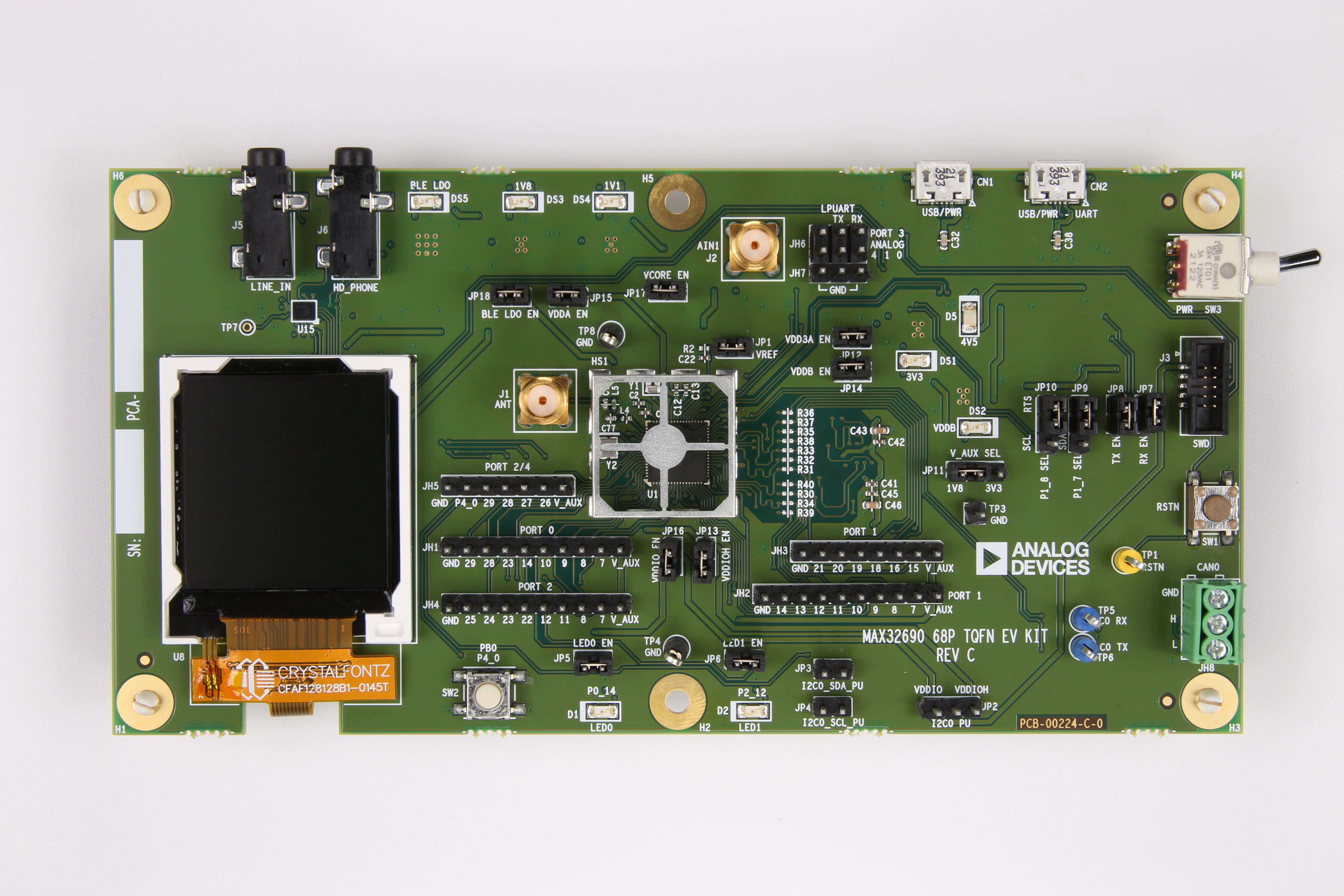
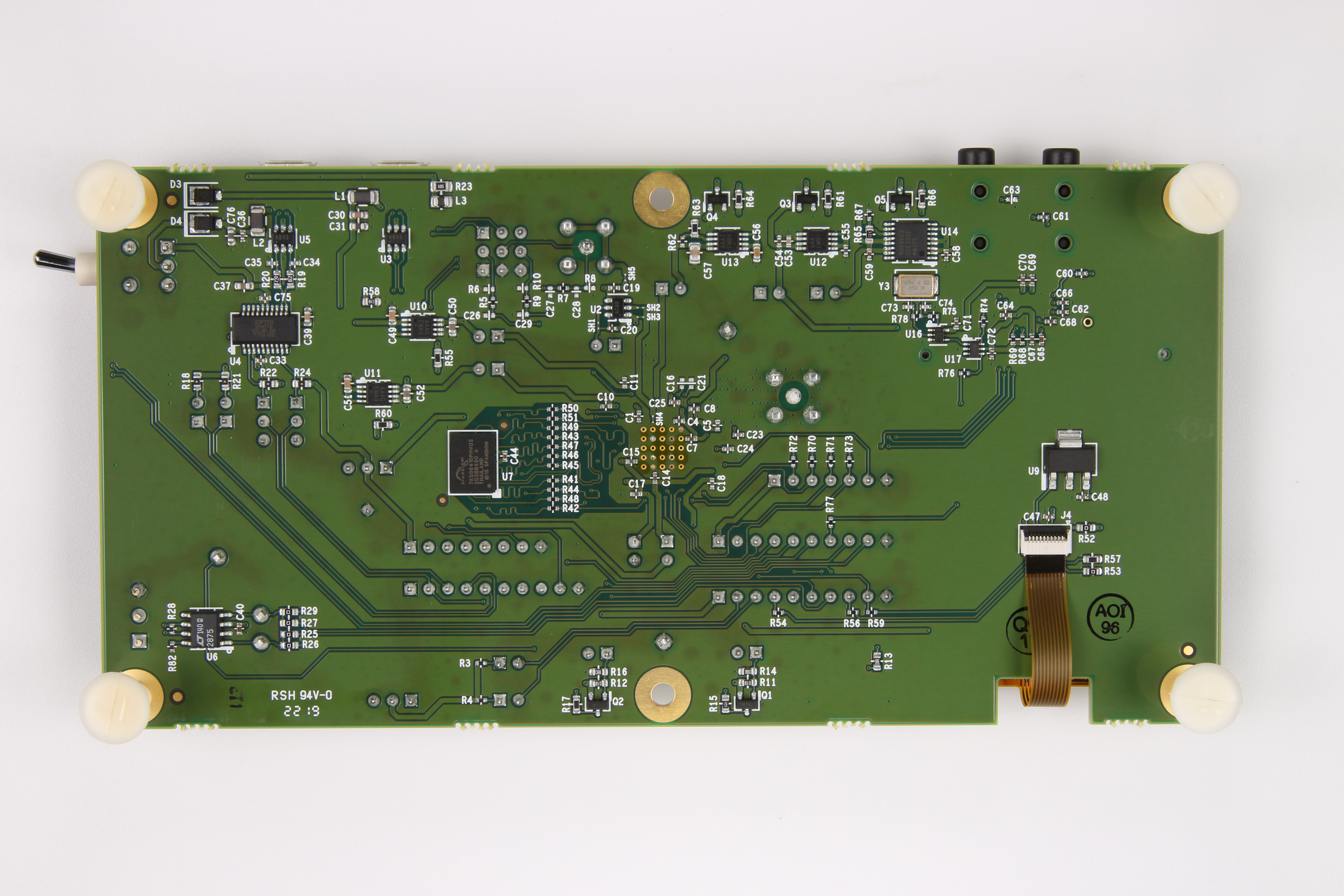
MAX32690評価用キット
資料
ソフトウェア
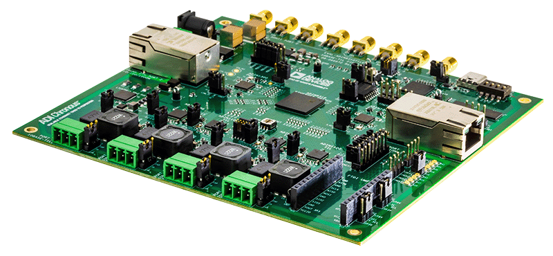
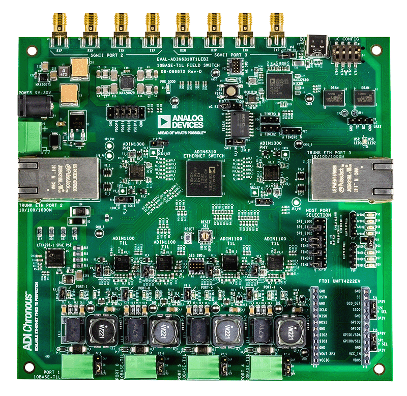
ADIN6310 Field Switch Reference Design User Guide