EMI-/EMC-Ready SerDes—Basic Test Strategies and Guidelines
Abstract
Electromagnetic interference (EMI) and electromagnetic compatibility (EMC) testing is an important part of design verification for serializer/deserializer (SerDes) devices in automotive applications. EMI and EMC must be considered early in the design cycle to prevent needless design revisions. The following application note details helpful, basic concepts and guidelines on how to prepare your SerDes system for EMI/EMC testing.
A similar version of this article was published August 3, 2009 on AutoElectronics-online by Electronic Design.
Introduction
LCD video displays are becoming increasingly more common in automotive applications. Rugged design, small size, and low cost make them ideal for safety, navigation, and infotainment systems. LCD displays are digital and operate with discrete digital values for each pixel. Because the media/graphic sources that drive these displays are also usually digital, a digital link is the simplest and highest performance method to interface a video source with the display. The digital channel for this video link must provide a high bandwidth. For example, a 640 × 480-pixel color display operates at 30fps (frames per second). With only 6-bit resolution for each red, green, and blue pixel, the corresponding data rate is 640 × 480 × 30 × 18 = 166Mbps. The actual transmit speed must be one bit faster, as blanking times are required for proper operation. Many displays have many more pixels and/or a larger number of pixels per bit, quickly escalating this bit rate. Serializer/deserializer (SerDes) chipsets then take the parallel digital data and serialize it for transmission. Some devices, such as the MAX9209 serializer, keep the red, green, and blue data separate, resulting in one serial channel for each of the three primary colors, plus a fourth channel for the clock. Other devices, such as the MAX9247 serializer, combine this data into a single serial channel with an embedded clock signal. Both of these approaches increase the fundamental frequency of the transmission significantly. Although the increase in frequency can cause problems, it is easy to provide a properly shielded and impedance-matched transmission medium for the serialized signal.
EMI Testing
EMI testing is necessary in automotive applications to ensure that select systems do not corrupt the other systems around them. Testing is done for radiated emissions and conducted emissions. Radiated emissions testing primarily utilizes antennas and checks a system's ability to radiate through free space to other systems. An improperly designed SerDes system can fail to meet EMI specifications. In contrast, conducted emissions testing is primarily done with voltage and current probes on a system's power-supply line. Because SerDes systems seldom connect directly to the power-supply line, conducted emissions is rarely an issue.
EMC Testing
Similar to EMI testing, EMC testing in automotive applications is performed to ensure a system is not corrupted by other peripheral systems. This is significant due to the large number of electronics systems in today's automobiles, all of which have currents, impedances, and operating frequencies across a broad spectrum. Bulk current injection (BCI), which is utilized for EMC testing, is a particularly rough on the system being tested. Although BCI testing specifications and methods vary among automotive manufacturers, they generally involve strong external fields across frequencies from a few MHz up to 1GHz.
Pixel Clock Frequency Selection
Proper pixel clock selection can have a significant impact on EMI. A SerDes video link, like any high-speed digital device, radiates detectable levels of EMI at integer harmonics of the clock frequency. In automotive applications, the limit for EMI radiation varies with frequency. Many automobile manufacturers specify rather stringent limits across specific frequency bands. For example, 433MHz is the frequency used for remote keyless entry (RKE), and is usually one of the tightest areas of EMI specification. Considering a system with a pixel clock frequency of 33MHz, the 13th harmonic is located at 429MHz, which can cause interference in the 433MHz RKE band. Selecting a slightly lower frequency of 32.7MHz moves the 13th harmonic to 425MHz, creating a more comfortable frequency margin.
Common Elements for SerDes PCB EMI/EMC Testing
- Grounding any IC is an important design practice. For a SerDes system, however, it is of the utmost importance. All ground pins must have low impedance and be connected to a solid ground plane. It is not recommended to split the PCB into multiple planes. A copper poured plane on the PCB component side, plus a continuous copper plane immediately below, is standard practice. Keep the topside copper pour away from matched impedance traces. Keeping at least 3x the trace-to-trace spacing of the differential pair is a good approach.
- Consider using multiple vias per ground connection. The parasitic inductance of vias is a large contributor to nonideal behavior. Doubling up on ground vias reduces the inductance, thereby improving performance.
- Bypassing any IC is usually important, but for a SerDes system, it is extremely important. Similar to the grounding recommendations, power-supply pins must see low AC impedance from the power supply. This holds especially true for low-voltage differential signal (LVDS) lines, I/O supply pins, and the supply pins used for phase-locked loop (PLL) circuitry. Using two bypass capacitors per pin is recommended. These two capacitors are usually 10x to 100x different in value (e.g., 0.1µF and 1nF). The smallest capacitor should be closest to the supply pin it must decouple/bypass.
- Consider using ferrite beads at the supply pins of the SerDes system. Again this is particularly practical for LVDS lines, I/O supply pins, and PLL supply pins, but this can be applied to any power-supply pin. Ferrite beads reduce the ingress and egress of high- frequency energy. Choose a ferrite bead that has a peak impedance of 100Ω to 600Ω and is rated for at least 100mA.
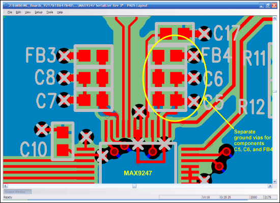
Figure 1 depicts a close-up of a PCB layout using the MAX9247 serializer. The components of interest are FB4, C6, and C5, which are arranged in a column with their silkscreen reference designators located just to the right of the respective component outline. Along the bottom of Figure 1 is one corner of the MAX9247. FB4 has its right-side terminal connected through a via to an embedded ground plane. The left terminal of FB4 is wired down across C6 and C5, and then to pin 27 of the MAX9247, which is the serializer's VCCPLL power-supply node. Note that the trace connecting FB4, C5, and C6 is kept wide to achieve a lower inductance. As this trace narrows in order to meet the pin pitch of the MAX9247, a small polygon of copper is used between C5 and the MAX9247 to keep the trace as wide as possible, yet as close as possible to the serializer. Furthermore, the grounding of C5 and C6 shows that each capacitor has its own via to the ground plane (to the right of each component). The top copper plane is flooded with ground, providing a direct, low-inductance path from C6 and C5 to pin 26 of the MAX9247, which is the serializer's PLLGND.
Serializer-Specific Recommendations
Preventing the serializer from radiating EMI requires a few basic concepts. Generally, the serializer is not particularily sensitive to EMC testing; however, its output requires a balanced transmission pair with constant impedance. Most serializer ICs are optimized for 100Ω impedance. Other values near this range are acceptable if dictated by an unchangeable element in the design. If the serializer outputs leave the box and enter the car's wiring harness, these outputs must withstand shorts to the battery. The easiest solution is to AC-couple each output with a 0.1µF capacitor. To do this, however, a DC-balanced serializer, such as the MAX9209, MAX9217, or MAX9247, would be required. A non-DC-balanced device may be used as well, but the system design must then ensure that the required bias voltage is provided externally, which is not usually a practical approach. Finally, a common-mode choke is often included at the output of the serializer before it leaves the PCB. This provides a bit of protection from common-mode noise radiating out of the serializer assembly. However, common-mode chokes usually provide only very minimal improvement, and should not be used where its insertion loss (nominally 1dB) could compromise the reliability of the link.

Figure 1. Recommended bypassing and grounding details for the MAX9247 serializer.
Deserializer-Specific Recommendations
As with a serializer, preventing the deserializer from radiating EMI requires the test/design engineer to follow a few basic concepts and guidelines. Protecting the deserializer assembly from EMC events also requires the review of a few basic concepts, because the deserializer can be vulnerable to EMC and can also radiate EMI.
Common-mode chokes are often included at the input of the deserializer close to where the differential signal enters the PCB. The common-mode choke helps minimize the pickup of common-mode noise. Common-mode chokes must have a low differential insertion loss at the system-selected operating frequency. The deserializer input requires a balanced transmission pair that has constant impedance. Most deserializer devices are optimized for 100Ω impedance, though other values near this range are acceptable if dictated by an unchangeable element in the design.
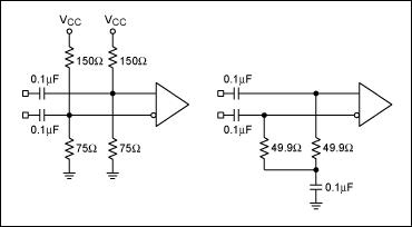
If the deserializer inputs require AC-coupling, this can be done after the common-mode choke. Again, these capacitors are used only on DC-balanced deserializers, such as the MAX9236 and the MAX9248. The differential pair requires termination into a 100Ω differential impedance as close as possible to the receiver-side IC. While the differential impedance is kept at 100Ω, the common-mode impedance must also be kept low. Either a Thevenin termination system can be used or a pair of 50Ω resistors in series with the middle node bypassed to ground. Both of these approaches are shown in Figure 2. Using a pair of 50Ω resistors is the preferred method for EMI/EMC testing, because:
- it allows the IC to set its own DC bias,
- it does not inject VCC noise into the termination, and
- it consumes no power.

Figure 2. Methods of proper LVDS termination (left: Thevenin configuration; right: serial 50Ω resistor configuration).
Connector and Cable Harnesses
The connector and cables used in a SerDes system are considered a pivotal part of the system, and their impact on EMI and EMC testing is significant. Common practice in automotive applications dictates that PCB receptacles and cable connectors are usually sourced from a single manufacturer for both sides of the link. Connectors must maintain constant impedance and provide a shielded interface for optimized performance. Additionally, they must allow only a single insertion polarity and a positive lock to guarantee manufacturability and reliability.
The cable too must provide constant impedance, and its harness requires heavy shielding to prevent radiation. If a multipair cable is used, each cable pair requires individual shielding. The ubiquitous CAT5 cable is generally inadequate for automotive SerDes use.
Connector and cable systems are available from many manufacturers. Products from Rosenberger, JAE, or Hirose are recommended.
In some systems, the shield of the connector is grounded on only one side of the link, and the other is connected to ground with a capacitor (typically 0.1µF). This coupling prevents DC-current flow in the cable shield due to differences in ground potential.
Other EMI Sources
Another EMI source in a SerDes video link is the output of the deserializer. These outputs are CMOS logic levels with relatively high-speed edges. If the CMOS logic outputs are not properly shielded, they too can cause EMI radiation. A great way to reduce the EMI from LCD-panel logic signals is to use a deserializer with spread-spectrum technology, such as the MAX9242, MAX9244, MAX9246, MAX9248, or MAX9250. These deserializers offer a variety of operating modes, data width, and operating frequencies to fit most system requirements.