Design Note 318: Efficient Dual Polarity Output Converter Fits into Tight Spaces
Introduction
This Design Note describes a compact and efficient ±5V output dual polarity converter that uses a single buck regulator. The topology shown features 3mm maximum circuit height, high efficiency and low output voltage ripple on a 5V output—important considerations for many battery-powered, handheld and noise-sensitive devices. This combination of features is not easily achievable with other commonly used dual polarity topologies. For instance, one alternative topology, a flyback converter using a boost regulator, is relatively inefficient, requires a bulky (5mm or taller) transformer and generates high output voltage ripple. Another alternative, using two buck regulators, incurs both the cost of the additional regulator and the cost of the PCB real estate it occupies.
The single buck regulator topology shown here requires few components. To reduce the maximum circuit height, it uses two power inductors instead of a transformer. In the absence of the transformer core, the coupling capacitor allows energy to pass between the positive and negative sides of the circuit while maintaining a voltage potential between the two inductors, indirectly regulating the negative output.
12V Input, ±5V Output, Only 3mm High
A dual polarity output converter uses a buck regulator, such as the LT1956 or LT3431. Both of these are 500kHz, 1.5A/3A peak switch current monolithic switchers. Figure 1 shows a 12V battery input (9V to 16V input with 36V transients) to ±5VOUT dual polarity output converter using the LT1956EFE. Figure 2 shows the same circuit with twice the load current rating using the LT3431EFE.
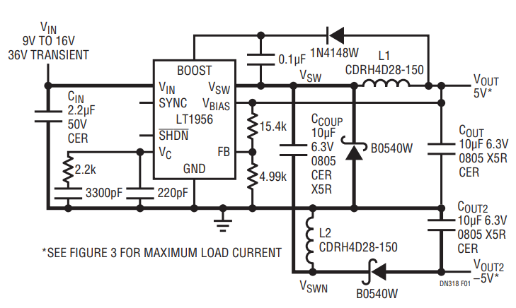
Figure 1. LT1956 9V to 16V Input (with 36V Transients), ±5V Output, 3mm Height All Ceramic Dual Polarity Converter with High ΔI/Δt Crucial Layout Path Indicated in Bold.

Figure 2. LT3431 9V to 16V Input (with 36V Transients), ±5V Output, 3mm Height All Ceramic Dual Polarity Converter with High ΔI/Δt Crucial Layout Path Indicated in Bold.
Typical Bucks with Second, Negative Outputs
The dual polarity output configuration is similar to the typical buck regulator with a second, negative polarity output added to the circuit using a coupling capacitor and a second inductor, catch diode and output capacitor. The duty cycle remains the same as the typical buck regulator with the same VIN and VOUT. The positive 5V output maintains its low output voltage ripple characteristic from the buck regulator, but some of the current available for that output is rerouted through the coupling capacitor to the second output. The coupling capacitor charges up to and maintains a voltage equal to the output voltage (5V). This induces the same voltage and hence the same current ripple across both inductors. However, the average current in L1 is the 5V load current while the average current in L2 is the negative load current.
The maximum load current, shown in Figures 3 and 6, is reached when the sum of the peak inductor currents is equal to the peak switch current rating of the regulator, 1.5A (LT1956) or 3A (LT3430), or the negative output loses regulation. The peak switch current region is to the right of the peak in the curves. To the left of the peak in the curves, 1.5A and 3A cannot be reached by increasing the negative load current without losing over 3% regulation on VOUT2.
IOUT(MAX) [5V] = 1.5/3 – IOUT2 [–5V] – 2 • ILP-P/2
(for peak switch current region)
ILP-P = (VIN – 5VOUT)• DC/(L • 500kHz)
Extremely low negative load currents can also cause a loss of regulation on VOUT2 as seen in Figures 4 and 7. In order to maintain relatively good regulation in low load applications, a preload resistor on VOUT2 of 12mA (LT1956) or 25mA (LT3430) may be required. Feedback is derived directly from VOUT so that its load current can go to zero without a loss of regulation.

Figure 3. Maximum Load Current Conditions for Figure 1.

Figure 4. The Negative Supply (VOUT2) Maintains ±5% Regulation.

Figure 5. The Efficiency of Figure 1.

Figure 6. Maximum Load Current Conditions for Figure 2.

Figure 7. The Negative Supply (VOUT2) Maintains ±5% Regulation.

Figure 8. The Efficiency of Figure 2.
Conclusion
The LT1956- and LT3431-based dual polarity output converters provide power for ±5V loads with a single buck regulator. This design offers size and efficiency advantages over other dual output designs, especially those that require a transformer.
Author
