Design Solutions 4 - High Accuracy, Differential to Single-Ended Conversion for Wide Range Bipolar Input Signals Bipolar Differential to Single-Ended Converter
Specifications
| Parameter | Circuit (Measured) |
LTC2400 | Total Units |
| Input Voltage Range | ±2.45 | V | |
| Zero Error | 22 | 1.5 | µV |
| Input Current | See Text | ||
| Nonlinearity | ±2.5 | 4 | ppm |
| Input-Referred Noise (without averaging) | 6.5 | 1.5 | µVRMS |
| Input-Referred Noise (averaged 64 readings) | 1 | µVRMS | |
| Resolution (with averaged readings) | 22.2 | Bits | |
| Overall Accuracy (Uncalibrated) | 17.1 | Bits | |
| Supply Voltage | 5 | 5 | V |
| Supply Current | 2.1 | 0.2 | mA |
| CMRR | 118 | dB | |
| Common Mode Range | 0 to 5 | V |
Operation

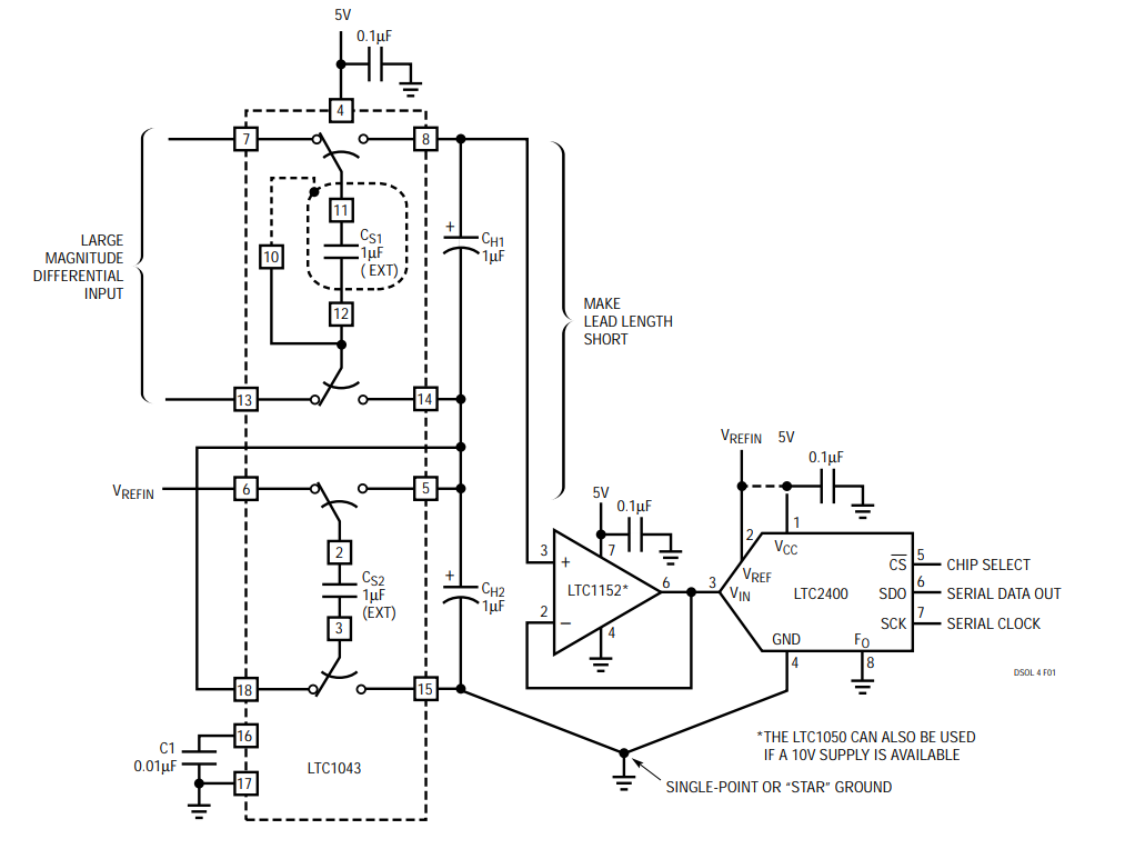
The circuit in Figure 1 is ideal for wide dynamic range differential signals in applications that have a 5V supply. The circuit uses one-half of an LTC1043to perform a differential to single-ended conversion over an input common mode range that includes the power supplies. This half of the LTC1043 samples a differential input voltage, holds it on CS1 and transfers it to capacitor CH1. The voltage on CH1 is buffered, applied to the LTC2400’s input and converted to a digital value.
A reference voltage is applied to the LTC2400’s VREF pin and the LTC1043’s Pin 6. The remaining half of the LTC1043 divides the reference voltage by two with a high degree of accuracy. This VREF/2 voltage is applied to the bottom of CH1, centering the LTC1043’s output voltage at midscale. This allows the converter to accept bipolar input voltages that swing about a VREF/2 point when operating on a single supply.
The LTC1043 achieves its best differential to single-ended conversion when its internal switching frequency operates at a nominal 300Hz, as set by the 0.01µF capacitor C1 and when 1µF capacitors are used for CS1, CS2, CH1 and CH2. Each of these four capacitors should be a film type such as mylar or polypropylene. Conversion accuracy is enhanced by placing a guard shield around CS1 and connecting the shield to Pin 10 of the LTC1043. This minimizes nonlinearity that results from stray capacitance transfer errors associated with CS1. Consult the LTC1043 data sheet for more information. As is good practice in all high precision circuits, keep all lead lengths as short as possible to minimize stray capacitance and noise pickup.
The circuit in Figure 1 improves on unbuffered LTC1043 circuits, providing an order of magnitude improvement in linearity (±2.5ppm) by buffering the voltage on CH1. The circuit also improves linearity by buffering the voltage on CH1 with an LTC1152 operating at unity gain. If a 10V supply is available, the LTC1050 can be used instead of the LTC1152.
As stated above, the LTC1043 has the highest transfer accuracy when using 1µF capacitors. Using any other value will compromise the accuracy. For example, 0.1µF will typically increase the circuit’s overall nonlinearity, and degrade CMRR by an order of magnitude.
Another source of error is thermocouple effects that occur in soldered connections starting with the LTC1043’s input traces and ending with the connections to the LTC2400’s input and ground pins. Any temperature changes in any of the low level circuitry’s connections will cause perturbations in the final conversion result. Their effects can be minimized by controlling thermal gradients between pairs of connection by judicious placement of heat sources, components and copper heat spreaders under the pads and by insulating the circuit against moving air
The circuit’s input current is dependent on the input signal’s common mode voltage. The input current is approximately – 100nA at VIN(CM) = –2.5V, 100nA at VIN(CM) = 2.5V and 0µA at VIN(CM) = 0V. The values may vary from part to part. Figure 1’s input is analogous to a 2µF capacitor in parallel with a 25MΩ connected to ground. The LTC1043’s nominal 800Ω switch resistance is between the source and the 2µF capacitance.
Authors
