Developing Power-Optimized Applications on the MAX78002
Abstract
Power consumption is a key factor for edge Artificial Intelligence (AI) applications where the entire system is powered by small battery cells and is expected to operate for months without recharging or replacing the batteries. The MAX78002 ultra-low power AI microcontroller is built to target such applications at the edge of the IoT. In this document, various options are described to enable users to develop power-optimized applications on the MAX78002 and benchmarking examples are presented.
Introduction
The MAX78002 is an advanced system-on-chip featuring an Arm® Cortex®-M4 with FPU CPU and an ultra-low-power deep neural-network accelerator. This architecture enables the development of very power-efficient AI applications in energy-constrained environments. The MAX78002 provides a variety of options and operation modes to create low-power applications. The following sections contain an overview of such options with practical examples and actual measurements on the MAX78002 EV kit. For more information and details, see [5].
MAX78002
The MAX78002 is a follow-on product to the MAX78000 with additional computing power and memory in the new generation of artificial intelligence (AI) microcontrollers built to enable the execution of neural networks at ultra-low power and live at the edge of the internet-of-things (IoT). This product combines the most energy-efficient AI processing with Analog Device's proven ultra-low power microcontrollers. The hardware-based convolutional neural networks (CNN) accelerator enables battery-powered applications to execute AI inferences while spending only microjoules of energy. The MAX78002 features an Arm Cortex-M4 with floating-point unit (FPU) microcontroller for efficient system control and an ultra-low power deep neural network accelerator. A RISC-V core is also integrated and can execute application and control codes as well as drive the CNN accelerator. Figure 1 shows the top-level architecture of the MAX78002.
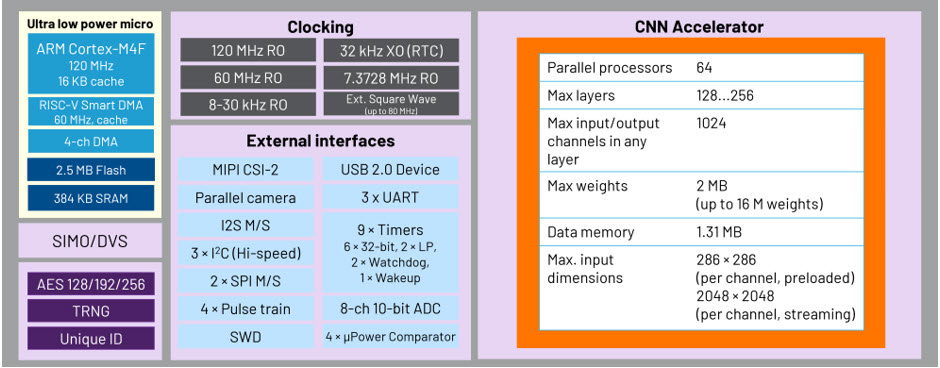
Figure 1. The architecture of the MAX78002.
The MAX78002 evaluation kit (EV kit) provides a platform for leveraging device capabilities to build new generations of AI products. It features onboard hardware like a digital microphone, serial ports, digital video port (DVP) and camera serial interface (CSI) camera module support, and a 3.5-inch touch-enabled color thin-film transistor (TFT) display [2]. It also includes the circuitry to monitor and display the power level on the secondary TFT display. The MAX34417 [3] monitors the voltage and current of the MAX78002 and reports the accumulated power to the MAX32625, which is used as the power data processor that also controls the power display, as shown in Figure 2.
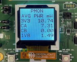
Figure 2. The power monitor.
The power monitor operates in two modes; instantaneous, which displays average power, supply current, and voltage, and windowed energy accumulation, which measures the CNN power or total system power based on triggering events. Instantaneous measurements are typically used for quick, coarse estimates of the power level. Windowed measurements are ideal to measure the accumulated energy between the user-defined start and complete instances. These events are triggered by the toggling of two general purpose inputs/outputs (GPIOs) of the MAX78002 (P1.6 and P1.7) connected to the MAX32625 power data processor. For more information on using the power monitor, see [4].
A large and a small model example are chosen to perform most measurements in this document:
- cifar-100-mobilenet-v2-0.75: A 73-layer implementation of a MobileNetV2 type architecture with 1.34M weights (56% of the weight memory capacity) for image classification.
- kws20_v3_1: A 9-layer 148K weights (6% of the weight memory capacity) network for keyword spotting.
Furthermore, there is a tabular snapshot of CNN power measurement for all published SDK examples at the end of this document for reference.
Note: The measurement results presented in this application note are based on running example codes on a MAX78002 EV kit. The actual result on the user's platform and specific applications can vary. A variation of ±3.8% in energy/power measurement of a benchmark example is observed on a sample set of eight different EV kit boards.
MAX78002EVKIT Jumper Setting for Power Measurement
To use the power monitor to measure the power in different modes of operation, the MAX78002 EV kit jumpers are set as shown in Table 1 and Figure 3.
| Jumper | Setting | Description |
|---|---|---|
| JP1 | IN | 3V3 MON |
| JP2 | OUT | 3V3 SW PM BYPASS |
| JP3 | IN | CNN MON |
| JP4 | OUT | VCOREA PM BYPASS |
| JP5 | OUT | VCOREB- PM BYPASS |
| JP6 | OUT | VREGO_A PM BYPASS |
| JP7 | IN | VBAT |
| JP8 | IN | VREGI |
| JP9 | BOTTOM | VREGI - 3V3PM |
| JP10 | LEFT | VDDIOH - 3V3PM |
| JP11 | IN | VDDA |
| JP12 | IN | VDDIO |
| JP13 | IN | VCOREB |
| JP14 | IN | VCOREA |
| JP29 | BOTTOM | VDDB PWR SEL |
| JP34 | RIGHT | I2S VDD |
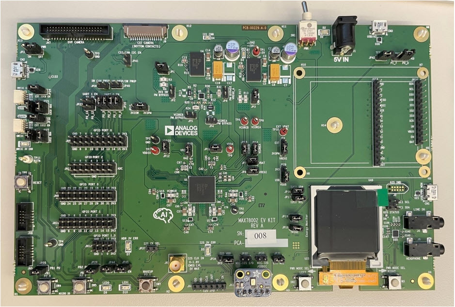
Figure 3. MAX78002 EV kit jumper setting for power measurement.
MAX78002 Clocks and Operating Modes
The MAX78002 supports different clock sources and low power operating modes that can be jointly configured to achieve optimized power and performance. This application note provides a brief description of each mode to guide the reader to set up the modes according to the desired application. For more detailed descriptions, see [5].
Clocks
The MAX78000 includes multiple configurable clocks used by different peripherals. Configure the clock sources as needed to select the combination of performance and power efficiency. The selected system oscillator (SYS_OSC) is the clock source for most internal blocks. The following oscillator sources are available and can be selected as SYS_OSC:
- Internal Primary Oscillator (IPO) – 120MHz:
- IPO is the fastest frequency oscillator and draws the most power. When entering low power mode (LPM), this oscillator can be powered down.
- Internal Secondary Oscillator (ISO) – 60MHz:
- This is a low-power internal secondary oscillator that is the power-on reset (PoR) default for SYS_OSC.
- Internal Nano-Ring Oscillator (INRO) – 8kHz to 30kHz:
- INRO is an ultra-low power internal oscillator that can be selected as the SYS_OSC and is always enabled. The frequency is configurable to 8kHz, 16kHz, or 30kHz (default).
- Internal Baud Rate Oscillator (IBRO) – 7.3728MHz:
- This is a very low-power internal oscillator that can be selected as SYS_OSC. This clock can optionally be used as a dedicated baud rate clock for the UARTs.
- Internal Phase Lock Loop (IPLL) - 100MHz/200MHz:
- Operating from the external 25MHz crystal, the IPLL provides a 100MHz oscillator that can be used as the system clock as well as a 200MHz clock for the CNN clock. Note that when the CNN clock is higher than 50MHz, use the pipeline (enabled by default in the synthesis tool).
- External Base Oscillator (EBO) – 25MHz:
- It is an available external oscillator that can be selected as the SYS_OSC. It is also used for the IPLL and can be used for the ADC clock.
- External Real-Time Clock Oscillator (ERTCO) – 32KHz:
- This is an extremely low-power internal oscillator that is the default clock for the real-time clock (RTC) and can be also selected as SYS_OSC.
- External Clock (EXT_CLK) – up to 80MHz:
- An external clock up to 80MHz can be used as the SYS_OSC.
| API | Description |
|---|---|
| int MXC_SYS_ClockSourceEnable (mxc_sys_system_clock_t clock) | Enables a clock source without selecting it; the following sources are available: MXC_SYS_CLOCK_IPO MXC_SYS_CLOCK_IBRO MXC_SYS_CLOCK_ISO MXC_SYS_CLOCK_IPLL MXC_SYS_CLOCK_EBO MXC_SYS_CLOCK_INRO MXC_SYS_CLOCK_ERTCO MXC_SYS_CLOCK_EXTCLK |
| int MXC_SYS_Clock_Select (mxc_sys_system_clock_t clock) | Selects the clock source to be used for SYS_CLK. See [6] for the complete list. |
| void SystemCoreClockUpdate(void) | Updates the system core clock according to the selected clock source. |
| void MXC_SYS_ClockEnable (mxc_sys_periph_clock_t clock) | Enables peripheral clocks. See [6] for the complete list. |
| void MXC_SYS_ClockDisable (mxc_sys_periph_clock_t clock) | Disables peripheral clocks. See [6] for more information. |
Operating Modes
As summarized in Table 3, the MAX78002 includes multiple operating modes to optimize performance and power, like the MAX78000. For more information on the operation modes, check the Operating Mode section in [6].
| Operation Mode | Oscillators | System RAM | CNN Quadrants | CNN RAM | Peripherals | API |
|---|---|---|---|---|---|---|
| Active | All available | Available | Active, Configurable | Active, Configurable | Available | |
| Sleep | All available | Available | Active, Configurable | Active, Configurable | Available | MXC_LP_EnterSleepMode() |
| LPM | ISO, IPO, ERTCO, INRO IBRO (default) |
0,1: Retention 2,3: Available |
Active, Configurable | Active, Configurable | Available | MXC_LP_EnterLowPowerMode() |
| UPM | IBRO, ERTCO, INRO |
Retention | Optionally off | Selectable retention | Retention, LPUART0, LPTMR0-1 LPWDT0, LPCOMP0-3, GPIO, WUT, RTC available |
MXC_LP_EnterMicroPowerMode() |
| Standby | ERTCO | Retention | Off | Selectable retention | Retention, WUT, RTC, COMP0, GPIO available |
MXC_LP_EnterStandbyMode() |
| Backup | ERCO | Configurable retention |
Off | Selectable retention | Off, WUT, RTC, COMP0, GPIO available |
MXC_LP_EnterBackupMode() |
| Power Down | Off | Off | Off | Off | Off, Configurable P3.0/1 |
MXC_LP_EnterPowerDownMode() |
VCOREA Supply Voltage
The nominal supply voltage for VCOREA is 1.1V, which provides a sufficient margin for operating the CNN with the large and compute-intensive models at the upper range supported by the architecture. The MAX78002 EV kit is supplied with VCOREA regulated to 1.1V from the factory. The minimum CNN input supply (VCNNXRAM and VCNNX) is 0.99V [1] and should be the same as VCOREA. Generally, it is possible to lower the VCOREA to 1V to achieve about 15% power saving. However, 1V operation depends on the CNN model and operating conditions. Carefully test the functionality to ensure proper operation for the specific use case. In this document, several measurements are performed, both with VCOREA = 1.1V and 1V, to highlight the differences.
On the MAX78002 EV kit, VCOREA is set to 1.1V (R15 = 21KΩ in [2]) by default. To change it to 1V, modify the R15 to 14.7KΩ.
Power Consumption in Different Operation Modes
In developing an application, switch the MAX78002 to different operation modes and schedule the tasks accordingly to save power. Figure 4 shows the power consumption in different modes. ACTIVE and SLEEP power are measured using the ISO oscillator at 60MHz. Other low power modes employ ERTCO (32kHz) during the sleep period (API default). GPIOs are set to input. The power consumption in UPM, STANDBY, BACKUP, and POWER DOWN modes is lower than the accuracy range of the power monitor to measure. Refer to the data sheet [1] for more information.
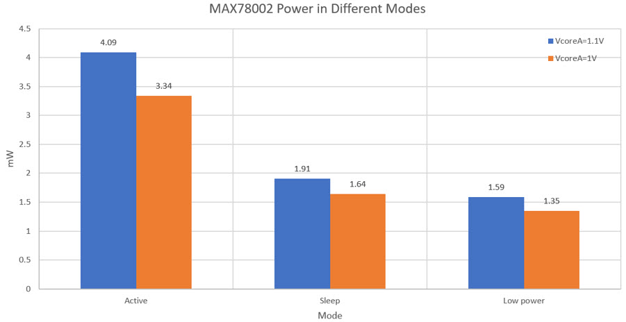
Figure 4. Power consumption in different operation modes.
Bootup time (defined as the time from power-up to the start of executing the main code) and wakeup time are also tested (Figure 5). The wakeup time and bootup time are measured with the default power-on clock (ISO at 60MHz).
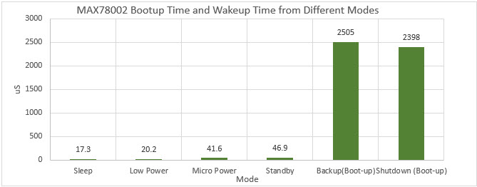
Figure 5. Bootup and Wakeup time at different frequencies.
Wakeup Configuration
In operating modes other than the ACTIVE mode, configure the wakeup source to re-enter the ACTIVE mode. The LPM mode is regularly used during inference. After completion of inference, the CNN wakes up the Arm or RISC-V, as needed. The following code snippet shows the sequence:
Example of  Arm wakeup from LPM by CNN:
    load_input(); // Load data input
    cnn_start(); // Run inference
   // ARM goes to LPM and waits for CNN interrupt to wakeup
    SCB->SCR &= ~SCB_SCR_SLEEPDEEP_Msk; // SLEEPDEEP=0
     while (cnn_time == 0)
     __WFI(); // Wait for CNN

Example of  RISC-V wakeup from by CNN:
    load_input(); // Load data input
    cnn_start(); // Run inference
    // RISC-V sleeps and waits for CNN interrupt to wakeup
    while (cnn_time == 0)
    asm volatile("wfi"); // Wait for CNN
For more information on the list of wakeup sources and configurations, see [6] and section 4.4 of [5].
CNN Power
The core of an AI application is the inference, performed by the CNN accelerator. Depending on the application, the inference can happen continuously on incoming data or periodically at certain time intervals. Loading kernels (weights) are typically done once and they are retained in CNN memory. However, depending on the application and duty cycle, choose to reload the weights every time prior to running the inference.
The CNN power consumption is measured in three phases:
- Loading weights: Happens once to load weights into CNN memory in active mode.
- Loading input data: Every time there is a new inference.
- Inference: Operates on input data and generates the result.
CNN Clock Source and Frequency
By default, the IPLL clock is enabled and used as the clock source of CNN at 200MHz by the synthesis tool. To save energy during loading the weights and input of data, the clock is reduced to 50MHz (divide by 4) before loading and setting back to 200MHz (divide by 1) prior to the start of inference.
The following command-line options are available in the synthesis tool to control the clock source, clock frequency, and pipeline:
- [--no-pll]: It uses the IPO as the clock source. The IPO clock is 120MHz with a fixed internal divide by 2 generating a 60MHz clock for CNN. In this mode, the CNN clock divider is set to 1 for both loading and inference.
- Note that the pipeline is enabled by default with this option, even if the clock-div is also set to 4 or higher. This results in unnecessary excessive power consumption as the pipeline is only needed for a higher than 50MHz CNN clock.
- If the pipeline is also disabled [--no-pipeline], it sets the CNN clock divider to 2 (30MHz) as the highest allowed CNN clock frequency when using IPO without the pipeline. In this case, the same clock divider is selected for loading input and weights, as well as inference.
- [--no-pipeline]: Disables the use of CNN pipeline. The IPLL is still selected as the clock source. However, it adjusts the clock frequency to 50MHz (divide by 4) for both loading and inference.
- [--max-speed]: It uses the maximum speed (200MHz) for both loading and inference with IPLL.
- [--clock-div k]: This option sets the CNN clock divider k (k can be 1,2,4,8,16) for inference. The clock divider for loading weights and inputs remains at 4. Note that if the inference divider is set to 4 or higher, the pipeline is no longer needed and should be explicitly disabled to save power.
The effect of changing the clock source and frequency on energy and time of loading weights and input data is demonstrated in Figure 6 to Figure 9 for VCOREA = 1.1V and VCOREA = 1V. A similar energy profile is observed on both tested benchmarks (cifar-100-mobilenet-v2-0.75 and KWS20-v3-1).

Figure 6. Loading weights energy and time for mobilenet with different clock sources and frequencies.
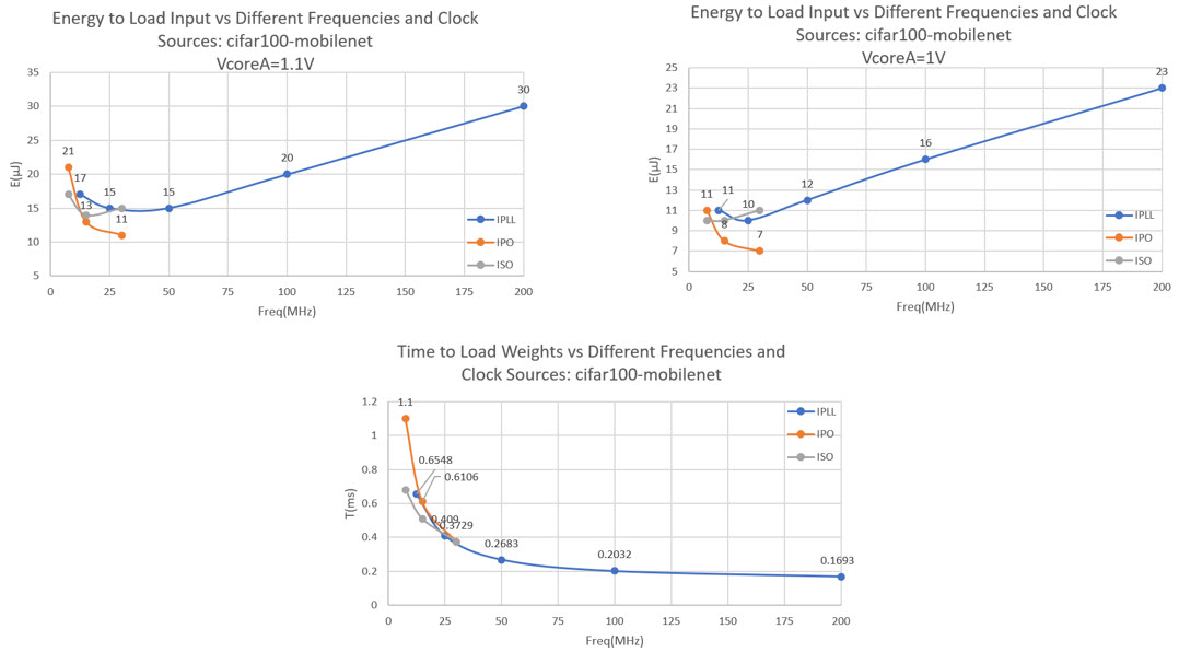
Figure 7. Input loading energy and time for mobilenet with different clock sources and frequencies.
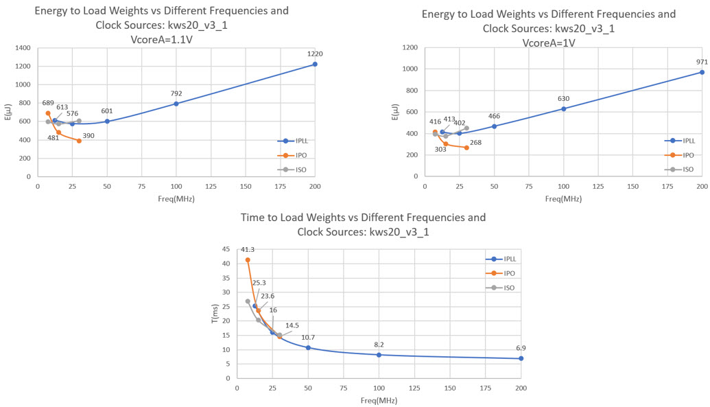
Figure 8. Loading weights energy and time for mobilenet with different clock sources and frequencies.

Figure 9. Input loading energy and time for KWS20 with different clock sources and frequencies.
As shown, using the IPO with CNN clock divider equal to 2 (30MHz) provides the lowest loading energy while increasing the loading time. Depending on the application, choose different configurations for loading weights, which happens once (if weights are retained), and loading input, which is performed prior to each inference.
CNN Pipeline
CNN can run at up to 200MHz when using IPLL clock to generate inference results in the shortest time. The trade-off is the power consumption at higher clock frequencies. In MAX78002, enable the CNN pipeline when the CNN clock is set to higher than 50MHz. Enabling the CNN pipeline increases the inference power consumption and is recommended only for CNN frequencies above 50MHz. The synthesis tool enables the CNN pipeline by default and uses the IPLL clock at 200MHz as the CNN clock source. Select the option [--no-pipeline] as described before to disable the pipeline for CNN operation up to 50MHz.
Figure 10 and Figure 11 demonstrate the effect of the clock source and frequency on the inference energy and time for VCOREA = 1.1V and VCOREA = 1V. The pipeline is only enabled when IPLL clock at 100MHz or higher is selected. In general, using IPLL at the highest clock (200MHz) results in the lowest energy and fastest execution.
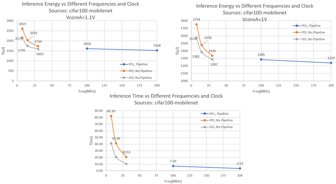
Figure 10. Inference energy and time for mobilenet with different clock sources and frequencies.

Figure 11. Inference energy and time for KWS20 with different clock sources and frequencies.
Retaining Weights in CNN Memory
Each of the four CNN RAMs (the CNN weights storage) can be configured to retain the weights in case of UPM, BACKUP, or STANDBY (not retained by default). The CNN configuration registers are lost in any of those power-saving modes (except SLEEP and LPM) regardless of the CNN retention setting and must be reloaded.
The following code snippet shows how to enable the CNN RAM retention for UPM, BACKUP, or STANDBY. Once CNN memory retention is configured, the weights are maintained. For every activity cycle, only bias and CNN configuration are reloaded, and new inference is performed on new input data. Figure 12 shows the power consumption in different modes with or without CNN memory retention. The effect of disabling the CNN clock is also reported.
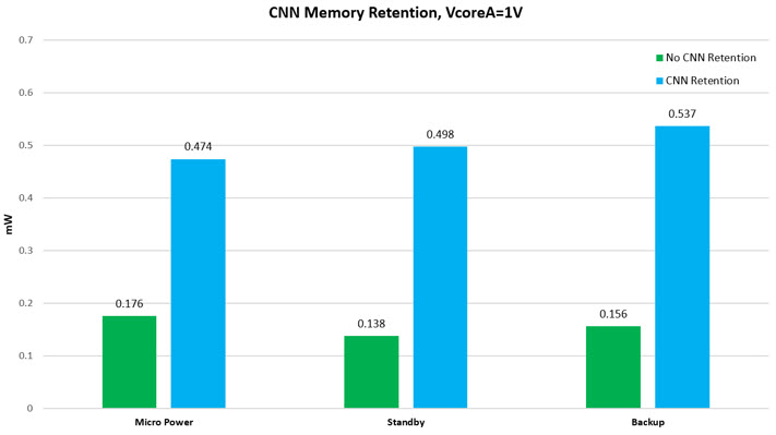
Figure 12. CNN memory retention power.
For some low-duty cycle applications, choose to reload the weights in every activity cycle to further reduce power consumption during sleep. In this case, consider the effect of extra power used to repeatedly reload weights (like Figure 6 for large and small network examples).
Example: Loading weights and configuring CNN with CNN Mask RAMs retention

// Load kernels once
 cnn_init(); // Bring state machine into initial state
 cnn_load_weights(); // Load kernels
 cnn_load_bias(); //
 cnn_configure(); // Configure state machine

// Enable source of waking up, e.g. push button
 PB_RegisterCallback(0, buttonHandler);
 …

while(1){
    // Disable CNN
     cnn_disable();
     // CNN Retention on:
     MXC_GCFR->reg2 = 0xf0 << MXC_F_GCFR_REG2_CNNX16_0_DATA_RET_EN_POS;

     // Go to sleep, e.g. Micro Power.
     MXC_LP_EnterMicroPowerMode();

     // Waking up after interrupt, e.g. push button – CNN memory is retained for kernels.
     // bias & configuration are not retained.

     // Enable CNN, set the clock source and CNN clock divider,
     // To save power for loading, divider can be set to 4
     cnn_enable(MXC_S_GCR_PCLKDIV_CNNCLKSEL_IPLL,
                         MXC_S_GCR_PCLKDIV_CNNCLKDIV_DIV4);

     cnn_init(); // Bring state machine into consistent state
     cnn_load_bias();
     cnn_configure(); // Configure state machine

     // Load input data
     load_input();

     // Change CNN clock divider before inference if needed
     // CNN clock: PLL (200 MHz) div 1
     MXC_GCR->pclkdiv = (MXC_GCR->pclkdiv & ~(MXC_F_GCR_PCLKDIV_CNNCLKDIV |
                                          MXC_F_GCR_PCLKDIV_CNNCLKSEL)) |
                                          MXC_S_GCR_PCLKDIV_CNNCLKDIV_DIV1 |
                                          MXC_S_GCR_PCLKDIV_CNNCLKSEL_IPLL;
     cnn_start(); // Run inference
     SCB->SCR &= ~SCB_SCR_SLEEPDEEP_Msk; // SLEEPDEEP=0
     __WFI(); // Wait for CNN Interrupt to wake for sleep

}
Measurement Results for SDK Examples
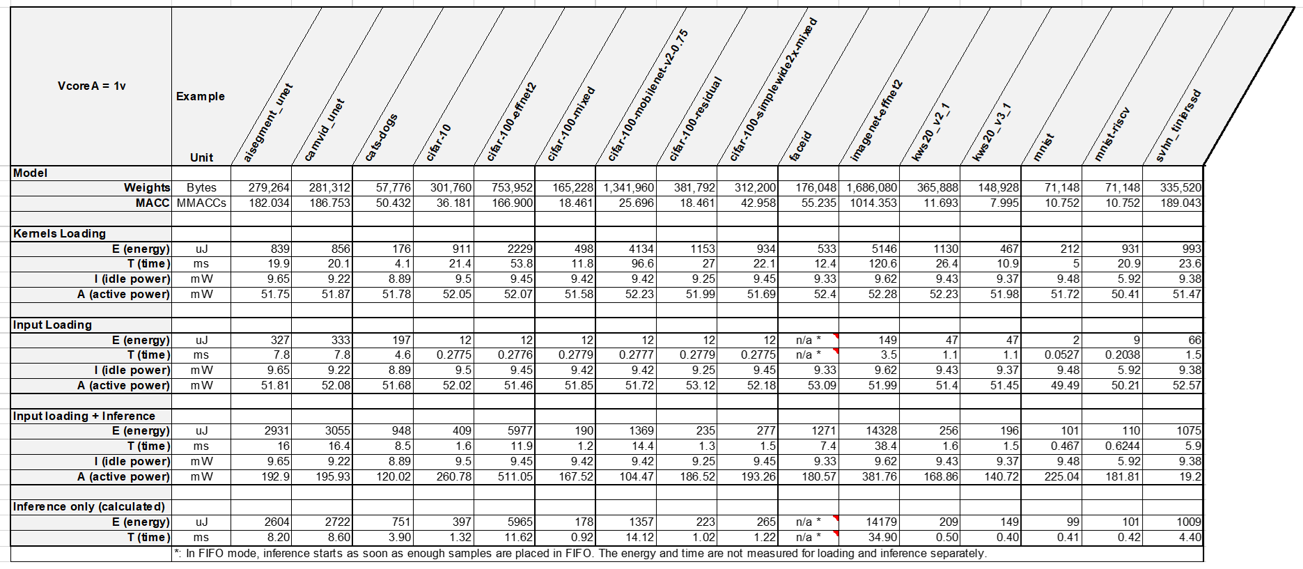
The MAX78002 SDK examples are regenerated with option --energy in the synthesis tool. This option adds the code to toggle the GPIOs routed to the power monitor circuitry to enable the power measurement in the CNN Power Mode. Table 4 shows the result for loading weights, loading input, and inference. The VCOREA is set to 1V in this experiment. Other configurations are the default.
Table 4. Measurement Results on Multiple SDK Examples

Summary
This application note introduces some of the power optimization techniques supported by the MAX78002 to create a low power application and the result of measurement. The following summary highlights general recommendations to improve the power consumption:
- Faster is often better for inference energy. Using higher clock rates (e.g., IPLL at 200MHz) makes the execution faster and the impact of constant static power is reduced, improving the overall power consumption.
- The CNN clock source and divider can be different during loading and inference. The lowest energy consumption for loading data and weights is observed with IPO at 30MHz. The trade-off is the increased loading time.
- Take advantage of UPM, BACKUP, and STANDBY when there is no activity. Consider LPM when the ARM Cortex M4 can sleep while critical peripherals continue to run.
- If the duty cycle of activity is not very low, load kernels (weights) once and retain them in memory to avoid reloading energy in UPM, BACKUP, and STANDBY modes. Otherwise, consider the energy of reloading the weights in every activity cycle. See Figure 12 for CNN memory retention energy.
- Make sure to turn off the CNN clock after CNN processing is complete and turn it on before accessing CNN again in the next activity period.
- Reduce VCOREA from 1.1V to 1V to lower the power consumption, when possible. Use caution to make sure the CNN operates correctly over the target application conditions.
参考电路
2 MAX78002 Evaluation Kit Data Sheet
4 MAX7800x Power Monitor and Energy Benchmarking Guide
6 Developing Power-optimized Applications on the MAX78000