MAXQ1065
推荐新设计使用具有ChipDNATM的超低功耗加密控制器,适用于嵌入式器件
用于信任根、身份验证、安全引导和固件更新、加密以及TLS支持的加密功能
- 产品模型
- 4
产品详情
- 使用NIST P-256曲线的ECC计算引擎
- FIPS-186 ECDSA
- NIST SP800-56Ar3密钥交换,使用静态统一模型(0e, 2s, ECC CDH),使用SHA-256进行一步密钥派生
- 使用SP800-90B/A标准进行板载EC密钥生成
- SHA-2计算引擎
- NIST FIPS-180-4 SHA2-256、HMAC-SHA-256
- 具有128和256密钥大小的AES计算引擎
- ECB、CBC、CCM、GCM密码模式
- CBC-MAC、CMAC消息认证代码
- 使用SP800-90A/B标准进行板载AES密钥生成
- 真随机数发生器(TRNG)
- 符合NIST SP800-90A/C标准
- NIST SP800-90B熵源
- 安全通信
- TLS/DTLS 1.2握手和记录层
- ECDSA身份验证
- ECDHE密钥交换
- AES-GCM或CCM记录层
- 基于SP800-56Ar3的密钥交换
- TLS/DTLS 1.2握手和记录层
- X.509 v3证书支持
- 根证书和设备证书存储
- 板载证书链验证
- 在支持的曲线上进行ECDSA验证
- 用于主机微控制器通信的高速接口
- 10MHz SPI,提供模式0或模式3操作
- 具有ChipDNA PUF加密功能的8KB用户闪存阵列
- 唯一、不可更改的工厂编程ID号
- 防篡改输入可检测系统级入侵
- 安全工厂配置服务
- 12引脚、3mm x 3mm TDFN封装
- -40°C 至 +105°C,1.62V 至 3.63V
- 低功耗工作:待机模式下为100nA(典型值)
ChipDNA是Maxim Integrated Products, Inc.的商标。
DeepCover是Maxim Integrated Products, Inc.的注册商标。

MAXQ1065是一款安全协处理器,提供整套加密功能,用于信任根、相互认证、数据机密性和完整性、安全引导、安全固件更新以及通过通用密钥交换和批量加密或完整的TLS支持进行安全通信。该器件集成了用于存储用户数据、密钥、证书和计数器的8KB安全存储空间,以及用户定义的访问控制和生命周期管理。器件还有可配置的输出引脚和防篡改输入引脚。可通过标准SPI接口访问命令。
MAXQ1065具有低功耗,适合电池供电的应用,而且尺寸非常小,引脚数大幅减少,可轻松集成到医疗和可穿戴设备中。其使用寿命和工作范围都很适合长期部署在恶劣环境中。MAXQ1065的生命周期管理便于在器件的主要生命周期阶段采用灵活的访问控制规则。该器件还提供安全密钥加载协议和安全出厂预编程。
DeepCover®嵌入式安全解决方案将敏感数据隐藏在多层先进的安全保护之下,从而提供非常安全的密钥存储。为了防止设备级安全攻击,实施了侵入性和非侵入性对策,包括主动芯片屏蔽、使用ChipDNA PUF技术的密钥加密存储以及外部可调用的算法子例程。
应用
- 反克隆、反伪造、功能和使用控制
- 证书管理
- 相互认证
- 安全引导、安全固件更新
- 安全通信:密钥交换、TLS
- 安全数据存储
- 系统级防篡改保护和完整性
参考资料
数据手册 1
应用笔记 3
设计笔记 1
技术文章 2
视频 3


解决方案设计及宣传手册 2
在线研讨会 1
博客 2
思想领导力 3
模拟对话 1
ADI 始终高度重视提供符合最高质量和可靠性水平的产品。我们通过将质量和可靠性检查纳入产品和工艺设计的各个范围以及制造过程来实现这一目标。出货产品的“零缺陷”始终是我们的目标。查看我们的质量和可靠性计划和认证以了解更多信息。
| 产品型号 | 引脚/封装图-中文版 | 文档 | CAD 符号,脚注和 3D模型 |
|---|---|---|---|
| MAXQ1065GTC+ | Thin Dual Flatpack No Leads | ||
| MAXQ1065GTC+T | Thin Dual Flatpack No Leads | ||
| MAXQ1065GTC-C01+ | Thin Dual Flatpack No Leads | ||
| MAXQ1065GTC-C01+T | Thin Dual Flatpack No Leads |
| 产品型号 | 产品生命周期 | PCN |
|---|---|---|
|
4月 27, 2024 - 2400 ASSEMBLY |
||
| MAXQ1065GTC+ | 量产 | |
| MAXQ1065GTC+T | 量产 | |
这是最新版本的数据手册
工具及仿真模型
DeepCover® Security Lab
打开工具
评估套件
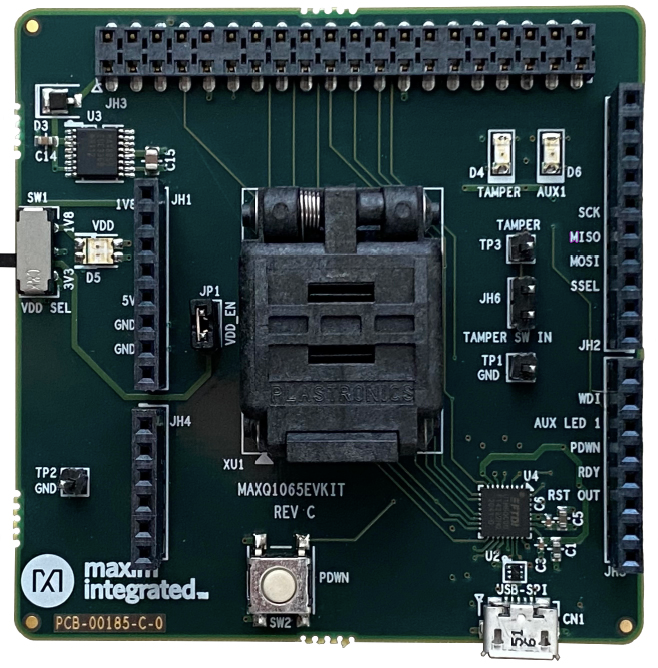
MAXQ1065评估套件
资料


Arduino Form-factor Development Platform Based on MAX32690 ARM Cortex-M4 Microcontroller
资料
软件


Software-configurable Analog and Digital I/O with 10BASE-T1L Evaluation and Development Platform
资料
软件


AD-ACEVSE22KWZ-KIT
资料
软件
最新评论
需要发起讨论吗? 没有关于 maxq1065的相关讨论?是否需要发起讨论?
在EngineerZone®上发起讨论