要約
This application note describes how to manage or suppress effects from external magnetic fields on transformers used for the 71M6541/71M6542/71M6543 family of electricity metering ICs. Special emphasis is placed on how to counter the effects of a strong DC magnet in the confined environment of a small meter enclosure.
Introduction
Background
The 71M6541/71M6542/71M6543 family of electricity metering ICs is designed to be used with current transformers (CTs), as traditionally used in single and polyphase meters, or shunt resistors that are connected to isolating remote sensor interfaces. The 71M6541/71M6542/71M6543 and 71M6545 remote sensor interfaces are normally connected to the 71M6541/71M6542/71M6543 ICs via small, low-cost pulse transformers.
Under the influence of a very strong DC magnetic field, a CT (i.e., the current transformer traditionally used in typical polyphase electricity meters) will saturate, and its output will be less than proportional to the applied current, resulting in revenue loss for the utility. Such saturation happens at high currents and is not easily detected.
Just like their analog counterparts, the CTs, pulse transformers can also be influenced by external magnetic fields. In the worst case, the transformers saturate and therefore lose their inductivity, turning them into low-ohmic loads to the drivers in the electricity metering device. This shorts out the differential drivers and consequently causes the supply power to collapse.
Consequently, a metering system consisting of a 71M6541/71M6542/71M6543 electricity metering IC and one or more 71M6601, 71M6103, or 71M6113 remote sensor interfaces connected to current shunt sensors is not entirely immune to magnetic fields. This application note describes how to manage or suppress effects from external magnetic fields on transformers used for the 71M6541/71M6542/71M6543/71M6545 family of electricity metering ICs. Special emphasis is placed on how to counter the effects of a strong DC magnet in the confined environment of a small meter enclosure.
Note that protection from magnetic effects cannot be implemented with a one-fits-all recipe. Each and every case is different, depending on whether AC or DC fields are present, whether the meter is immersed in a magnetic field or just exposed to a magnet placed on the outside, and whether the meter enclosure provides space to move the transformers away from the field source.
After a brief review of magnetic requirements for electricity meters, some basic terms of magnetic are presented. Mitigation methods are also presented, from the simplest low-cost techniques up to shielding techniques, and finally to using transformers with advanced magnetic materials.
Magnetic Requirements in Meter Standards
Traditionally, both ANSI and EN/IEC standards have required that electricity meters function at relatively benign levels of magnetic fields:
- ANSI C12.1, subclause 4.7.3.4, describes a test with a 6ft. x 6ft. Helmholtz coil operating at 100A turning AC and specifying a maximum deviation in Wh registration of ±1%.
- IEC 62053-11, Table 8, states an AC flux density of 0.5mT generated with a circular coil of 400A turns.
- IEC 62053-21, section 8.2.4, states a DC field strength of 1000A turns to be applied (as mentioned in Table 11, a registration error of 2% in a class 1 meter is permissible).
- EN 50470-1 specifies DC magnetic fields of 1,000A turns and describes a test coil (basically a DC magnet) that is to be applied to all accessible surfaces of the meter.
- EN 50470-1 refers to EN 61000-4-8 for AC magnetic fields (table-top equipment, AC magnetic field at mains frequency).
These requirements are not new and are the result of two considerations:
- Meters may suffer registration errors when operated in the vicinity (stray fields) of high-current AC circuitry.
- End customers may tamper with the meter using DC magnets.
Test conditions vary from standard to standard, but can be divided into two categories:
- Immersion method: The entire meter under test is exposed to a magnetic field generated by a large coil.
- Proximity method: A magnetic device is applied to the surface of the meter under test.
The applied test has implications on how the meter can be protected against the magnetic influence: When the proximity method is used, the geometric location of the sensitive components is of high importance. When the immersion method is used, the geometric location of the sensitive components is of minor importance, since the field will reach any place within the meter under test.
Domestic standards used in certain countries may contain country-specific requirements that apply on top of IEC or EN standards.
New DC Magnetic Requirements
More stringent requirements are emerging in certain markets due to the availability of very powerful rare-earth DC magnets that can be used for meter tampering.1 In the case of the German EHz meter, very stringent magnetic requirements are combined with a small physical form factor of the enclosure, making it even more challenging to meet the threat from the magnet.
Table 1 shows an example of the influence a DC magnet can have on an unprotected electricity meter. The results listed are from current measurements obtained from a meter operating with CTs with and without the presence of a DC magnetic field (generated by the test magnet prescribed by the German PTB requirements).2 The table shows significant errors at high currents that are the result of core saturation.
Consequently, CTs designed for operation in strong magnetic fields are often shielded against magnetic fields (with cost impact), or replaced with so-called "DC-tolerant CTs," adding significant cost and impacting phase accuracy over current and temperature.
| Current (A) | Display w/o Magnetic Field (A) | Display with DC Magnetic Field (A) | Display Error |
| 200 | 199.7 | 80 | -60% |
| 100 | 99.8 | 25 | -75% |
| 50 | 49.9 | 49.8 | -0.2% |
| 10 | 9.99 | 9.99 | 0% |
Some Basics of Magnetics
In electrical engineering, we think in terms of voltages that drive currents through resistors on a closed path. An analogy to this picture can be established when examining magnetic fields: Here, a magnet (or coil with electrical current flowing) takes the place of the voltage; free air or magnetic materials take the place of discrete resistors; and the induction is the equivalent of the electrical current. Magnetic field lines emanate from a pole of the magnet, penetrate open air or magnetic materials, and finally return to the opposite pole. Table 2 shows some magnetic properties and their physical units.
| Magnetic Element or Property | Symbol | Physical Unit | Description |
| Bar magnet | — | — | Source of a DC magnetic field |
| Field strength | H | A/m | Magnitude of a field generated by a magnet or by a current |
| Relative permeability | µr | Vs/Am | Conductivity for magnetic flux, compared to the permeability of vacuum (µ0) |
| Flux | Φ | Vs | The equivalent of the current in the electric field |
| Remanence | B | T | The "strength" of a DC magnet |
| Induction, flux density | B | T | B = Φ/A (flux per area) |
For a permanent magnet, the field lines are most concentrated around the poles, and the field strength decreases with increasing distance (r) from the poles. In relative proximity, the field strength will decrease at a rate between 1/r2 and 1/r3.
In vacuum, or air, the induction (B) is proportional to the field strength:
B = µ0 × H
Inside a magnetic material, the induction depends on the relative permeability of the material and the field strength:
B = µ0 × µr × H
In this equation, µr is strongly nonlinear. µr depends on the magnetic field strength (H), the material, the temperature, and other factors. For typical magnetic shielding materials, µr can be in the range of 80,000 in the linear range. For high applied field strengths, B will not increase any further, and saturation occurs.
Permanent magnets are usually characterized by dimensions, remanence, coercive field, and recoil permeability. The characteristics for a typical small rare-earth magnet are listed in Table 3.
| Property | Physical Unit | Magnitude | Description |
| Dimensions | mm | 40 × 18 × 12 | Geometrical dimensions |
| Remanence | T | 1.35 | — |
| Coercive field | A/m | 1 × 10⁶ | — |
| Recoil permeability | — | 1.05 | Permeability compared to free space |
Magnetic Properties of a Typical Metering System Based on the 71M6541/71M6542/71M6543
Meter Enclosure
Electricity meters are usually enclosed in plastic cases that are easily penetrated by magnetic fields. For all practical purposes pertaining to magnetic effects, the meters have no enclosures at all.
In a well-designed meter, the susceptible pulse transformers will be located as far away as possible from the sides of the enclosure.
Pulse Transformers
For standard applications, i.e., benign magnetic environments, Analog Devices recommends that pulse transformers based on ferrite cores are used in conjunction with the 71M6541/71M6542/71M6543 and the 71M6601/71M6103/71M6113 remote sensor interfaces. These transformers have the properties listed in Table 4. For manufacturer data and part numbers, contact an Analog Devices FAE or salesperson.
| Property | Physical Unit | Value | Comment |
| Core type | — | Toroid | — |
| Core dimensions (OD) | mm | 4.8 | Outer diameter |
| Core dimensions (ID) | mm | 2.3 | Toroid thickness 1.27mm |
| Initial permeability | — | 2700 | At 0mT flux density and room temperature |
| Maximum permeability | — | 4400 | At room temperature and at 200mT flux density |
| Saturation flux density | mT | 470 | At room temperature |
We can base some calculations on a typical pulse transformer based on ferrite core material (as described in Table 4). Saturation flux density is 470mT for this transformer. The signal current flowing through the windings will build up a flux density that should be much lower than the saturation flux density so that some flux density can be added by the magnetic field without causing saturation.
To calculate the flux density associated with the digital signal, we first calculate the field strength, which is given for a toroid core by the formula:
H = (i × N)/(2 × π × r)
N is the number of primary windings, i is the current supplied by the 71M6541/71M6542/71M6543/71M6545, and r is the radius of the torus. Using i = 12mA, N = 13, and r = 0.0024m, we determine H to be 10.35A/m.
The magnetization curve for the core material can then be used to estimate the flux density corresponding to the field strength (see Figure 1). The flux density corresponding to 10.35A is 170mT, which means that we have a theoretical budget of 470mT - 170mT = 300mT for flux generated by an external magnet before saturation is reached.
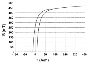
Figure 1. Magnetization curve for the core material.
Other Magnetic Components
When designing a meter for magnetic resistance, we must not lose sight of the fact that the meter may contain several other components that are susceptible to magnetic fields. Examples for such components are:
- Power supply transformers and/or chokes
- Ferrites used for EMC protection
- Transformers used in PLC circuits
- Transformers used in isolation circuits
Measures Against Magnetic Tampering
A variety of measures is available to the meter designer to fight magnetic interference. Measures are listed below in order of cost and effort:
- Event logging
- Strategic placement of components sensitive to magnetic fields
- Magnetic shielding
- Using transformers with alternative (high-saturation) core materials
These measures will be discussed in the following sections.
Event Logging
The first line of defense against transformer saturation from magnetic fields can be as simple as event logging.3 A magnetic event can lead to actions that can range from legal measures against the offender to disconnecting the load (using a cut-off switch) or penalizing the customer with maximum tariffs.
A variety of methods can be used to detect the presence of a permanent magnet. In the metering industry, the following methods are used:
- Reed relays: These tiny relays have ferromagnetic contacts that close when a magnetic field is applied. The contacts are usually routed to I/O pins of the meter IC.
- Hall-effect sensors: These analog sensors generate an output voltage proportional to the applied magnetic field. The output of the Hall-effect sensor is usually routed to an ADC or comparator input of the meter IC.
Demo code is available for the 71M6543F-DB and 71M6541F-DB demo boards that processes the dip of the supply voltage associated with transformer saturation and logs a tamper event. The code draws the distinction between a real power loss and tamper-induced power loss as follows:
- A loss of grid power is associated with a sag signal from the CE.
- A loss of board power caused by a magnetic tamper event is not connected to a sag event. The code will briefly execute in brownout mode and enable the remotes upon return to mission mode. If the magnetic tamper situation still exists, this will result in bit 0 being set in the VSTAT[2:0] register, and the MPU records this as a tamper event.
Placement of Components Sensitive to Magnetic Fields
If the proximity test is used for the meter, which is the case for the most severe magnetic applications, it makes sense to position the magnetically sensitive components, i.e., power supply transformers and chokes, as well as the pulse transformers as far away as possible from the accessible surfaces of the meter.
It was stated earlier that in relative proximity, the field strength of a magnet will decrease at a rate proportional to between 1/r2 and 1/r3. From that we can conclude that the field will be less than 1/4 at 2cm distance compared to 1cm distance from the magnet. This consideration makes placement the primary line of defense when event logging by itself is not sufficient.
Another consideration is the orientation of the transformers. Toroidal transformers tend to be more susceptible if the opening of the toroid core faces the source of the magnetic field. Figure 2 shows two different orientations of the core. The orientation shown on the left is less susceptible to the magnetic field from the magnet above.
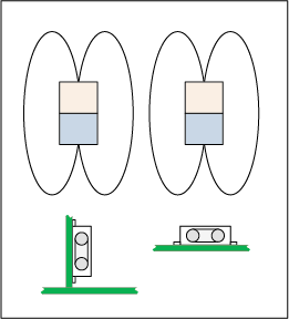
Figure 2. Orientation of ferrite core: vertical (left), horizontal (right).
Shielding
If the requirements for the meter go beyond event logging, and the options for geometrical arrangement of the pulse transformer(s) away from the meter enclosure sides are limited, shielding can be used to reduce the magnetic field. To save shielding material, it helps to arrange the transformers in a tight cluster, which is then surrounded by the shield.
The idea of magnetic shielding is that for a given field strength, the flux density will be highest in a highly permeable material. Shielding material will "soak up" the flux (like a sponge soaking up water), taking it away from susceptible components. However, once a certain field strength is reached, the shield will saturate and no longer carry a flux density proportional to the applied field. It is important to know the permeability and other magnetic properties of the components that are to be shielded. Just like the shielding material, these components will concentrate the magnetic flux, since their permeability is usually greater than that of free space.
Benign magnetic fields can be shielded efficiently with mu-metal, a material with high relative permeability (typically 70,000 to 80,000). Such materials are available in the form of foils or adhesive foils from various manufacturers (see the Tools and Resources section for links to manufacturers). These foils are easily cut and bent into the desired shape for laboratory tests. Once a good shield solution is found, a fixed stamped or machined shield in the form of a can or a box can be used.
When experimenting with magnetic shields, it is useful to observe a few guidelines, such as:
- Shields work best when the corners are not sharp, but bent smoothly.
- When forming a structure from foil, there should be considerable overlap where the two ends meet.
- Double or triple shields with thin gaps between them work better than solid material of double or triple thickness. Paper or plastic foil can be used to separate the layers of a shield.
Shielding efficiency is limited, especially when strong magnets are involved. In practical terms, shielding materials with high permeability tend to saturate early and therefore lose their shielding properties. For shielding against strong magnets, soft steel or other materials should be considered. However, efficient shielding is only possible when using high volumes of material, which makes the meter heavy and expensive.
Using Alternative Core Materials
Typical pulse transformers based on a ferrite material saturate at around 450mT to 500mT. These transformers offer a good solution in benign magnetic environments, when event logging can be used, or when transformer placement and/or shielding yield good results.
Not all magnetic scenarios can be met with this type of transformer. When large and powerful DC magnets are involved, sometimes the only solution is to use pulse transformers with higher saturation flux. Analog Devices has cooperated with transformer manufacturers to identify suitable core materials that offer a good combination of electrical properties, magnetic resistance, and economy.
After intense testing, two core materials were favored:
- MPP cores
- Hi-Flux cores
Analog Devices has cooperated with a magnetic manufacturer that can provide samples of transformers with Hi-Flux cores. For manufacturer data, part numbers, and part availability, contact an Analog Devices FAE or salesperson.
Some test results are presented in the Testing of Alternative Magnetic Materials section.
Shielding Simulations
Shielding simulations were performed with the Vizimag 2-D simulation tool. Shielding plates of 1mm thickness and with µr of 80,000 were assumed for these simulations.
No Shield
Without any shielding (see Figure 3), the field lines penetrate the PCB like air and generate a flux density of 92mT in the center and 75mT at a location 15mm off center.
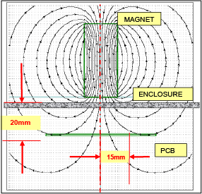
Figure 3. Magnetic field without shielding.
It is important to note that the simulation results of 92mT or 75mT will not be the achieved flux density in the transformer, once it is introduced into the field. The ferrite core will apply its own permeability and soak up the magnetic field lines. This will result in much higher flux density than what the simulations show for air.
Flat Shield
A flat shield reduces the flux density slightly. Bringing in a 40mm wide flat shield plate with µr = 80,000 and a thickness of 1mm reduces the flux density to 40mT (center) to 57mT (15mm off center). The effect of the shielding can be estimated by the distance between the field lines (see Figure 4), which is roughly twice as large in this simulation when compared with the simulation in Figure 3.
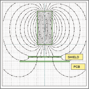
Figure 4. Magnetic field with flat shield.
Moving the shield up and down does not change the flux density significantly at the surface of the PCB. Interestingly, the thickness of the shield has only a minor influence on the flux density.
U-Shaped Shield
Bringing the sides of the shield down to form a U-shaped structure (see Figure 5) reduces the flux density to 25mT (center) and 29mT (15mm off center). The field lines tend to follow the mu-metal structure and penetrate the PCB only in two places.
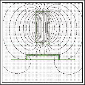
Figure 5. Magnetic field with U-shaped shield.
Further improvement is possible by elongating the sides of the U-shaped shield. In Figure 6, the field for a U-shaped structure with 12mm side length is shown. The field lines tend to avoid the cavity under the inverted "U" and leave the mu-metal structure at the very ends of the elongated side panels. This technique reduces the flux density to 15mT (center) and 12mT (15mm off center). As compared to the unshielded configuration, we have now achieved a more than six-fold reduction of the flux density.
Note that the shield now penetrates the PCB, which will make it necessary to provide cut-out slots in the PCB.
The results are then checked by introducing the toroid transformer cores with the physical properties given above, since the effect of the shielding ultimately shows as reduced flux density inside the cores (see Figure 7).
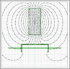
Figure 6. Magnetic field with elongated U-shaped shield.
The simulation shows maximum flux densities in the cores that now reach up to 2mT, which is below the saturation limit. By comparison, the flux density in the cores of the unshielded configuration (see Figure 8) reaches up to 200mT, which is close to the maximum flux that could be added based on the error budget established before.
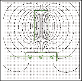
Figure 7. Magnetic field with elongated U-shaped shield and transformer cores.
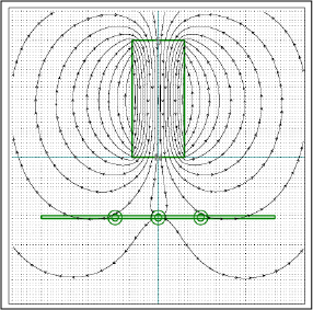
Figure 8. Magnetic field without shield and transformer cores.
Closed Shield
Better shielding results can be achieved by closing the shielding structure on all sides. This may not be practical due to assembly and isolation considerations, but in extreme cases it might be the only viable shielding solution. The 2-D simulation shows flux densities below 1.6mT in the cores (see Figure 9).
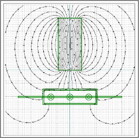
Figure 9. Magnetic field with closed shield and transformer cores.
Limitations of the Simulation
The simple simulation tools used for the examples shown above have limitations, such as:
- 2-D only: no awareness of the third dimension
- Toroids cannot be represented accurately in terms of their orientation. As shown in the graphs, the axes of the toroids are perpendicular to the paper (Z axis). In proper mounting position, i.e., with the transformer soldered to the PCB, the axes of the toroids would be parallel to the paper (Y axis).
- Most importantly, all shielding materials will saturate in the vicinity of a strong magnet and therefore lose their shielding properties.
These limitations mean that the results will not accurately predict the properties of an actual shield. More powerful 3-D simulation tools are available, and should be used where better accuracy is required.
Furthermore, shielding is complicated by the following considerations:
- Magnetic materials are conductive.
- High voltages are present at the transformers.
- 3-D structures are preferred for shielding.
- Clearance and creepage distances have to be observed.
Naturally, the meter designer will try to keep metallic structures away from the pulse transformers. This limits the application of shields to areas away from the pulse transformers. The fact that the transformers work best when placed inside three-dimensional shield structures also means that physical structures are limited: they cannot penetrate PCBs.
Shielding Tests
Shielding Tests on a EHz Meter
Tests were performed with an enclosure very similar to the one specified for the German EHz meter. This enclosure is 135mm long, 90mm wide, and 80mm deep. The tight dimensions (see Figure 10) pose a challenge to the meter designer, since any magnetic component can never be placed more than 45mm away from the outside of the enclosure.
For the test, the PTB standard magnet as specified in the EHz documents was used: The FNN Lastenheft EDL for the German EHz meter specifies a surface flux density of 380mT be applied to one of the accessible surfaces when the meter is installed for operation (proximity method). The recommended test method uses the Nd2Fe14B 280/167 magnet per IEC 60404-8-1 with a remanence of 1200mT (75mm × 50mm × 25mm in size), which is applied "broadside," i.e., with the 75mm × 50mm surface directly to the meter enclosure. This magnet can be applied to all surfaces except for the bottom, which is plugged into the meter panel.
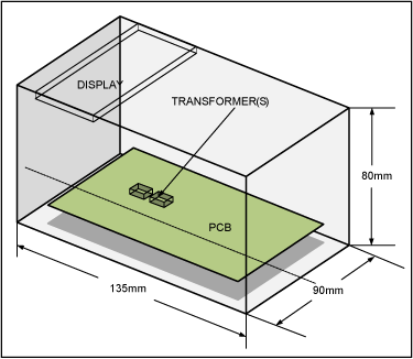
Figure 10. EHz enclosure dimensions with possible location for transformer(s).
Figure 11 shows the worst-case scenario where the magnet is applied sidewise to the meter enclosure.
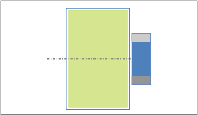
Figure 11. EHz enclosure with PTB magnet applied.
After lining the four side walls of the enclosure with steel shield of 0.75mm thickness (Figure 12), the transformer(s) could be arranged in the narrow green area along the longitudinal axis (with top side facing the side enclosure wall). The transformer(s) had to be "buried" at a depth of > 48mm from the top to avoid magnetic interference.
When applying a double-layer shield of 0.75mm thickness each and separated by 0.2mm plastic foil on the inside of the enclosure (Figure 13), the transformer(s) could be placed in the larger green area (with top side facing the side enclosure wall). Again, the transformer(s) had to "buried" at a depth of > 48mm from the top. This double-shield option adds considerable weight to the meter, but the material cost is moderate. However, the placement options for the transformer are restricted and do not leave a lot of freedom to the designer.
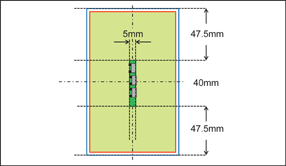
Figure 12. EHz enclosure with single shield.
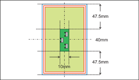
Figure 13. EHz enclosure with double shield.
Testing of Alternative Magnetic Materials
Transformer samples with cores based on MPP, Hi-Flux, and Sendust provided by a magnetics manufacturer that is cooperating with Analog Devices were tested. Preliminary testing showed that achievable distances from the PTB magnet could be reduced by 50% with respect to the distances achieved with standard ferrite cores.
As a proof of concept, transformers with the three core materials were mounted in a 71M6543F-DB demo board and then exposed to the PTB magnet, which was mounted at a variable distance from the transformers (Figure 14) and also with vertical offset 0mm or 10mm. Wh load lines were taken at various transformer distances.
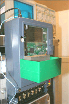
Figure 14. Meter test with PTB magnet.
Results are good for both Hi-Flux and MPP cores, even when the test magnet is a close as 17mm to the transformers (see Figure 15 and Figure 16).
By comparison, typical ferrite-based transformers already saturate when the PTB magnet is at a distance of 40mm.
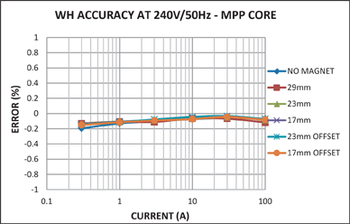
Figure 15. Wh load line for MPP core with PTB magnet.
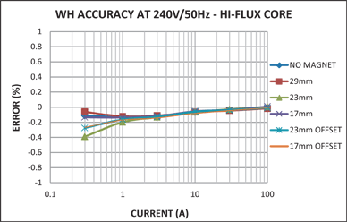
Figure 16. Wh load line for Hi-Flux core with PTB magnet.
Tools and Resources
Pulse Transformers
Simulation Tools
Some 2-D simulation tools are available inexpensively or as freeware:
3-D simulation tool:
Mu-Metal Material and Shields
Mu-metal foil samples and engineering kits are available from various sources. Typical engineering kits contain mu-metal foils that are coated with adhesive. A few sources are listed below:
Sources for stamped shield cans:
Test Magnets
One specialty manufacturer is listed below:
この記事に関して
{{modalTitle}}
{{modalDescription}}
{{dropdownTitle}}
- {{defaultSelectedText}} {{#each projectNames}}
- {{name}} {{/each}} {{#if newProjectText}}
-
{{newProjectText}}
{{/if}}
{{newProjectTitle}}
{{projectNameErrorText}}


