CN0588


概要
設計リソース
評価用ボード
型番に"Z"が付いているものは、RoHS対応製品です。 本回路の評価には以下の評価用ボードが必要です。
- EVAL-CN0588-EBZ ($300.00) DC to 10 kHz MEMS-Based IEPE Vibration Sensor
機能と利点
- Mechanically enclosed and machine mountable
- IEPE interface to retrofit into existing machines
- Power and data over a single wire, power comes from host
- Has a frequency range from DC up to 10 kHz and response within ±3 dB
- Resonant frequency around 12.5 kHz
製品カテゴリ
マーケット & テクノロジー
使用されている製品
参考資料
-
CN0588 User Guide2024/04/02WIKI
-
CN0588: DC to 10 kHz MEMS-Based IEPE Vibration Sensor (Rev. 0)2024/03/31PDF259 K
回路機能とその特長
Condition-based monitoring (CbM) enables early detection and diagnosis of machine and system abnormalities. CbM typically uses data from vibration, current, and temperature which provide key insights into the health of equipment ranging from motors and pumps to bearings and encoders. These machine health insights result in increased productivity, improved efficiency, and maximized uptime. Ultimately, by tracking the vibration analysis data over time, a fault or failure can be predicted, along with the source of the fault.
Vibration detection is the most popular method used in machine condition-based monitoring. This is done by collecting large datasets, which are used to identify a baseline operating point for the equipment in both normal operating modes and failure scenarios in order to provide an accurate understanding of machinery that requires monitoring. Once this information has been gathered, an algorithm or threshold detection procedure can be developed to monitor and analyze the equipment.
The integrated electronics piezoelectric (IEPE) standard is a prominent signaling interface standard for today's high-end piezoelectric and microelectronic mechanical systems (MEMS) vibration sensors.
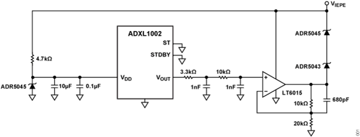
The reference design shown in Figure 1 is a MEMS-based IEPE vibration sensor optimized for condition-based monitoring applications. The solution has a current supply of 4 mA and an excitation voltage of 24 V to 28 V. This vibration sensor also features a DC voltage bias ranging from 8.75 V to 14.75 V, and a sensitivity of 60 mV/g.
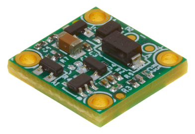
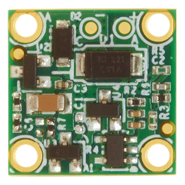
The board comes with a carefully designed mechanical enclosure, which houses the integrated sensor and ensures that high quality vibration data is extracted from the monitored asset.
Figure 1. CN0588 Simplified Block Diagram.
回路説明
The circuit shown in Figure 1 demonstrates a MEMS vibration sensing solution with included IEPE compatible interface circuitry at 8.75 V to 14.75 V bias and 4 mA current consumption.
Vibration Sensor Types Piezo Vs. MEMS
Piezoelectric (piezo) and microelectromechanical systems or MEMS are two different types of sensor technologies commonly used for various applications, including measuring physical parameters such as acceleration, pressure, and temperature. The choice between these technologies can impact the way the sensor responds to different input signals, including AC and DC signals, and how it affects the input bandwidth.
Traditionally, piezoelectric sensors have been the benchmark for vibration monitoring and are still the sensor of choice in the highest sensitivity applications, or where very high accelerations are involved. MEMS sensors were previously deemed unusable due to their limited bandwidth, g-range, and noise performance across frequency. However, recent advancements in MEMS sensor technology (especially with frequency response and noise performance) make MEMS sensors a viable alternative in many CbM applications.
Piezoelectric sensors may offer better noise performance than MEMS at higher frequencies, but at low frequencies MEMS sensors offer lower noise all the way to DC. Being able to measure these low frequencies is very useful for wind turbines, and other types of slow rotating machinery used in metal processing, pulp/paper processing, and food/beverage industries where slow rotating speeds of assets below 60 rpm (1 Hz) are common.
Overall, MEMS sensors are typically smaller, have a lower cost, lower power consumption, and now have a greater frequency response. Table 1 shows the key differences between these two sensor types.
| Key Considerations | Sensor Type | |
| Piezoelectric | MEMS | |
| Cost | $25 to $500+ | $10 to $30+ |
| Noise | <1 μg/√Hz to 50 μg/√Hz | 25 μg/√Hz to 100 μg/√Hz |
| 3 dB Bandwidth | 2.5 kHz to 30 kHz+ | 3 kHz to 20 kHz+ |
| Potential Battery Life | Short to medium | Medium to long |
| DC Response | No | Yes |
| Self-Test | No | Yes |
| Integrated Features | No | Yes |
Sensor
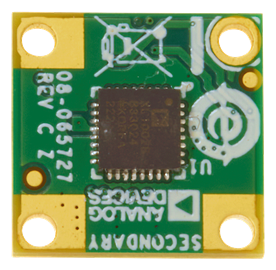
The core of the CN0588 is the ADXL1002 high frequency, single- axis MEMS accelerometer. The noise spectral density of the ADXL1002 is 25 μg/√Hz and its 3 dB bandwidth is 11 kHz with sensor resonance frequency of 21 kHz. The noise and bandwidth is comparable with a piezoelectric sensor while the ADXL1002 provides superior performance in temperature sensitivity, DC to low frequency response, phase response (and thus, group delay), shock tolerance, and shock recovery. The sensor has a linear (within ±0.1% FSR) measurement range of ±50 g, which is large enough to support the majority of CbM applications. The ADXL1002 also has an integrated full electrostatic self-test (ST) function and an overrange (OR) indicator that allow advanced system level features and are useful for embedded applications.
IEPE Interface
The IEPE interface is a 2-wire protocol, signal and ground. An instrument, such as data logger, supplies power via the signal line to the vibration sensor as current with an arbitrary voltage, typically between 10 V to 30 V. Because the signal line is supplied by a current source, the sensor device can modulate the acceleration data on the voltage rail. Therefore, the single wire can be used for both the power supply and the modulated output voltage of the sensor.
Figure 2 shows an example of the IEPE output with a bias voltage of approximately 11.75 V and a full-scale range swing of ±3 V.
Figure 2. CN0588 IEPE Signal.
Signal Conditioning
The circuit shown in Figure 1 must be supplied with a 4 mA constant current, which can be provided by an IEPE vibration measurement setup or a current source. Figure 3 depicts the signal conditioning circuitry of the CN0588. In this design, the ADR5045 precision voltage reference acts as the voltage source to the ADXL1002 as it generates a stable VDD to power the sensor. The LT6015 op amp is configured to amplify the filtered output of the ADXL1002 (2.5 V ± 2 V) by a factor of 1.5x. Then, the ADR5045 and ADR5043 are connected in series to introduce a DC offset of approximately 8 V. This configuration complies to the IEPE standard and operates within the voltage range of 8.75 V to 14.75 V. The VIEPE also supplies the LT6015 op amp in this signal conditioning circuit. A 4.7 kΩ resistor is used to regulate the voltage from the IEPE signal to at least the minimum current to supply the ADXL1002.
Figure 3. CN0588 Signal Conditioning Circuit.
バリエーション回路
The CN0588 can accommodate different MEMS sensors for different applications. The design is based on the ADXL1002, with a sensor resonant frequency of 21 kHz. However, the same circuit can be used as an IEPE compatible interface for other MEMS accelerometer in the ADXL100x family. When using another sensor, make sure to select the low pass filter cutoff frequency based on the chosen sensor's resonant frequency.
回路の評価とテスト
This section covers the setup and procedure for evaluating the CN0588. For complete details, visit the EVAL-CN0588-EBZ User Guide
Equipment Needed
- EVAL-CN0588-EBZ circuit evaluation board
- Current source (for example, Keithley 6220) or an IEPE-compatible DAQ such as the EVAL-CN0582-USBZ, EVAL-CN0540-ARDZ, or EVAL-CN0579-ARDZ
- Vibration shaker (for example, King Design 9363-ED-2F4K-5N)
- Signal generator
- SMA cable (10-32)
- BNC cable
Getting Started
- The basic steps for evaluating the functionality of the CN0588 follow:
- Mount the EVAL-CN0588-EBZ to the vibration shaker.
- Connect the SMA cable to the EVAL-CN0588-EBZ.
- Connect the other end of the SMA cable to the current source.
- Set the output constant current to 4 mA, and controlled voltage to 26 V.
- Connect the BNC cable to the vibration shaker.
- Connect the other end of the BNC cable to the signal generator (output).
- Set the frequency settings to your requirement.
- The voltage of the current source is the output. Without an external acceleration, the IEPE output should be around 12 V.
Figure 4. CN0588 Test Setup.
Test Result
To verify the performance of the CN0588 for vibration measurement applications, the circuit was tested using a vibration shaker (King Design 9363-ED-2F4K-5N), a reference sensor (PCBM352C67), and an IEPE vibration measurement platform (EVAL-CN0582- USBZ). The circuit is characterized for its frequency response. To validate the mechanical design of the casing, power spectral density test was simulated. Details and results of each test follow.
Frequency Response Measurement
As shown in Figure 5 the EVAL-CN0588-EBZ and the reference sensor are attached to the vibration shaker. The EVAL-CN0582- USBZ acts as the signal generator to control the vibration shaker from 100 Hz to 15 kHz, with step frequency of 100 Hz. The EVAL-CN0582-USBZ also serves as the current source for both the EVAL-CN0588-EBZ and the reference sensor. The output of the IEPE circuit and the reference sensor are recorded using the CN0582 evaluation software.
Figure 5. CN0588 Test Setup Using CN0582 as IEPE Vibration Measurement Platform.
Figure 6 shows the output of the frequency sweep of the sensor, where the resonant frequency measured is around 12.5 kHz. In this circuit evaluation and in any other high frequency vibration tests, mechanical signal path integrity is very important. There must be no attenuation (due to damping) nor amplification (due to resonance) of the vibration signal from the source to the sensor. The electrical and mechanical design of the CN0588 guarantees a flat mechanical response for the frequency range of interest, which is 10 kHz.
Figure 6. CN0588 Frequency Response.
Mechanical Enclosure Stress Test
The mechanical design of the CN0588 was tested through a power spectral density simulation. The von Mises stress criterion is commonly used in mechanical engineering to evaluate the yield criterion of the materials under complex loading conditions. Figure 7 shows the simulation results. Boundary conditions used for the simulation are as follows:
- Simulation type: Random Vibration
- External Load: Uniform Base Excitation
- Type: Acceleration
- Acceleration: 1 g2/Hz (Y-Direction)
- Damping ratio: 1%
- No. of Frequency: 20
- Lower limit: 1000 Hz
- Upper limit: 20000 Hz
Figure 7. CN0588 Mechanical Design Stress Simulation.