Guidelines to Implement CRC Programming for the MAX14915 Octal, Industrial, High-Side Switch
要約
The MAX14915 octal industrial high-side switch is a high-performance, feature-rich switch capable of delivering 15W nominal to each of eight loads. A microcontroller-compatible SPI provides access to many advanced features. For added safety, a hardware CRC circuit optionally protects this SPI interface against bit errors. This application note provides example C-code implementing CRC generation and detection algorithms in the microcontroller.
Introduction
The MAX14915 is a high-performance, 8-channel, industrial high-side switch with a rich and advanced feature set. An SPI interface allows a microcontroller to monitor and control most aspects of the MAX14915. To enhance robustness, a hardware cyclic redundancy check (CRC) circuit in the MAX14915 can optionally protect all data communication between it and a microcontroller against bit errors. However, enabling the CRC feature in the MAX14915 is not enough. The microcontroller must also implement the same CRC algorithm in software, both to append check bits to data being sent to the MAX14915, as well as to verify those being received from it. One way to accomplish this is to inspect the data sheet and use it to create custom firmware to implement the necessary CRC functionality. To provide a faster and proven solution, a series of functions are presented in this application note instead. They are written in C and should prove easy to port over to any common microcontroller. For detailed information of the MAX14915 pins, operating modes, and control registers, refer to the MAX14915 data sheet.
CRC Error Detection on the Serial Interface
The MAX14915 CRC error detection of the serial data can be enabled to minimize incorrect operation or misinformation due to data corruption of the SDI and SDO signals. If error detection is enabled, by setting the CRCEN pin = 1, then the MAX14915 does the following:
- Performs error detection on the SDI data that it receives from the microcontroller, and
- Calculates a CRC on the SDO data that it sends to the microcontroller and appends a check byte to the SDO diagnostics/status data that it sends to the microcontroller
This ensures that both the data that it receives from the microcontroller (setting/configuration) and the data that it sends to the microcontroller (diagnostics/status) have a low likelihood of undetected errors.
CRC error detection is supported for both SPI-addressed and daisy-chain operation modes, and for standard as well as burst read/write cycles.
Input Data on SDI (Read Cycle)
Setting the CRCEN input high enables CRC error detection. A CRC frame-check sequence (FCS) is sent along with each serial transaction. The 5-bit FCS is based on the generator polynomial X5 + X4 + X2 + 1 with CRC starting value = 11111. When CRC is enabled, the MAX14915 expects a check byte appended to the SDI program/configure data that it receives. Figure 1 shows the check byte format.

Figure 1. SDI check byte expected from microcontroller.
The 5-bit FCS bits CRC[4:0] are calculated on all the data sent in one SPI command including the three “0” in the MSBs of the check byte. Thus, the CRC is calculated from 8+3 bits up to 24+3 bits in case of a burst command. CRC0 is the LSB of the FCS.
The MAX14915 verifies the received FCS bits and if no error is detected, the MAX14915 sets the OUT_ output switches and/or changes device configuration per the SDI data. If a CRC error is detected, the MAX14915 does not change the OUT_ outputs and/or does not change the device configuration. Instead, the MAX14915 sets the COMERR logic output low, i.e., the open-drain COMERR output transistor is turned on.
If the mask register is set to enable CRCfault bit in the Global Faults register, the MAX14915 also sets the FAULT pin low to provide an interrupt to a microcontroller to further indicate a communication error on the SPI interface.
Output Data on SDO (Write Cycle)
The check byte the MAX14915 appends to the SDO data has the format shown in Figure 2 when the DAISY pin is low:

Figure 2. SDO check byte sent by MAX14915 in addressed SPI mode.
A1 and A0 are the levels for the A1 and A0 pins, while the THERR bit is set when a chip thermal shutdown event has occurred. CRC[4:0] are the five CRC bits the MAX14915 calculates on the SDO data, including the A1, A0, and THERR values. This allows the microcontroller to check for errors on the SDO data received from the MAX14915.
Source Code
This application note provides C source code for implementing a CRC generator and a CRC checker. The MAX14915 communicates with a microcontroller using either single-byte packets, or double-byte packets. The source code provides an encoder and decoder for each case:
- CRC5encode_2byte (for transmitting 2 bytes)
- CRC5encode_1byte (for transmitting 1 byte)
- CRC5check_2byte (for checking 2 bytes response from the MAX14915)
- CRC5check_1byte (for checking 1 byte response from the MAX14915)
Besides the choice of single-byte or double-byte packets for communication with the MAX14915, note that in these code examples "byte" is an alias for an 8-bit unsigned value, sometimes labeled differently, for example, UINT8.
Send1 is the first byte, and send2 is the second byte to send to the MAX14915. The code should transmit send1 followed by send2, then crc_code to the MAX14915.
crc_code = crc5encode (send1, send2);
The user should send 3 bytes, send1, followed by send2, and then crc_code, over the SPI interface. While the microcontroller sends configuration settings to the MAX14915 over the SPI interface, the MAX14915 simultaneously returns status information back to the microcontroller. This is the way to check if the crc_code received from MAX14915 is correct:
crc_ret = crc5decode (ret1, ret2);
The byte result "crc_ret" should be identical to the third byte received from the MAX14915.
Figure 3 and Figure 4 show data locations mentioned in the comments of the C functions. Download the spreadsheet
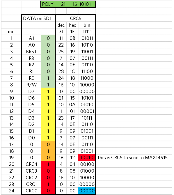
Figure 3. CRC5 data to send to MAX14915 on SDI.
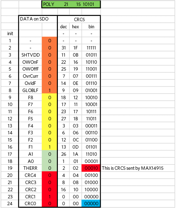
Figure 4. CRC5 data sent by MAX14915 on SDO.
public byte crc5encode(byte BYTE1, byte BYTE2)

{

byte crc5_start = 0x1f;

byte crc5_poly  = 0x15;

byte crc_result = crc5_start;
// BYTE1

for (int i=0; i<8; i++)

{

if( ((( BYTE1>>(7-i) ) 	&0x01) ^ ((crc_result  	& 0x10)>>4)) > 0  )  // IF(XOR(C6;BITAND(D5;2^4)/2^4)

{ crc_result = (byte) (crc5_poly ^ ((crc_result<<1) & 0x1f)); }  // BITXOR($D$1;BITAND((D5*2);31))

else

{ crc_result = (byte)((crc_result<<1)  	& 0x1f); }  // shift left, keep only lower 6 bits

}
// BYTE2

for (int i=0; i<8; i++)

{

if( ((( BYTE2>>(7-i) ) 	&0x01) ^ ((crc_result  	& 0x10)>>4)) > 0  )  //
IF(XOR(C6;BITAND(D5;2^4)/2^4)

{ crc_result = (byte) (crc5_poly ^ ((crc_result<<1)  	& 0x1f)); } // BITXOR($D$1;BITAND((D5*2);31))

else

{ crc_result = (byte)((crc_result<<1)  	& 0x1f); }  // shift left, keep only lower 6 bits

}

// 3 extra bits set to zero

byte BYTE3=0x00;

for (int i=0; i<3; i++)

{

if( ((( BYTE3>>(7-i) ) 	&0x01) ^ ((crc_result  	& 0x10)>>4)) > 0  )  // IF(XOR(C6;BITAND(D5;2^4)/2^4)

{ crc_result = (byte) (crc5_poly ^ ((crc_result<<1)  	& 0x1f)); } // BITXOR($D$1;BITAND((D5*2);31))

else

{ crc_result = (byte)((crc_result<<1)  	& 0x1f)); }  // shift left, keep only lower 6 bits

}

return crc_result;
}

byte crc5_decode(byte BYTE1, byte BYTE2)

{


byte crc5_start = 0x1f;

byte crc5_poly  = 0x15;

byte crc_result = crc5_start;
// BYTE1

for (int i=2; i<8; i++)

{

if( ((( BYTE1>>(7-i) ) 	&0x01) ^ ((crc_result  	& 0x10)>>4)) > 0  )  // IF(XOR(C6;BITAND(D5;2^4)/2^4)

{ crc_result = (byte) (crc5_poly ^ ((crc_result<<1)  	& 0x1f)); }  // BITXOR($D$1;BITAND((D5*2);31))

else

{ crc_result = (byte)((crc_result<<1)  	& 0x1f);                }  // shift left, keep only lower 6 bits

}


// BYTE2

for (int i=0; i<8; i++)

{

if( ((( BYTE2>>(7-i) ) 	&0x01) ^ ((crc_result  	& 0x10)>>4)) > 0  )  // IF(XOR(C6;BITAND(D5;2^4)/2^4)

{ crc_result = (byte) (crc5_poly ^ ((crc_result<<1)  	& 0x1f)); }  // BITXOR($D$1;BITAND((D5*2);31))

else

{ crc_result = (byte)((crc_result<<1)  	& 0x1f);                }  // shift left, keep only lower 6 bits

}
// 3 extra bits set to zero

byte BYTE3=0x00;

for (int i=0; i<3; i++)

{

if( ((( BYTE3>>(7-i) ) 	&0x01) ^ ((crc_result  	& 0x10)>>4)) > 0  )  // IF(XOR(C6;BITAND(D5;2^4)/2^4)

{ crc_result = (byte) (crc5_poly ^ ((crc_result<<1)  	& 0x1f)); }  // BITXOR($D$1;BITAND((D5*2);31))

else

{ crc_result = (byte)((crc_result<<1)  	& 0x1f);                }  // shift left, keep only lower 6 bits

}

return crc_result;
}
Conclusion
This application note has shown how to code CRC algorithms on a microcontroller communicating with a MAX14915 octal industrial high-side switch. This code was tested using the MAX14915EVKIT and the corresponding GUI. By taking advantage of the C code examples in this application note, the engineer has a proven solution to implement this extra data communication protection. In some cases, some benchmarking should be performed on the target microcontroller, especially if fast execution speed is a priority.