概要
リニア・レギュレータやスイッチング・レギュレータにおいて、従来と比べてよりノイズの小さい出力電圧を生成する方法は存在しないのでしょうか。本稿では、これを実現するために新たに設計された制御ループのアーキテクチャを紹介します。このアーキテクチャは、リニア・レギュレータにもスイッチング・レギュレータにも適用できます。また、ノイズを小さく抑えられるだけでなく、ノイズのレベルが出力電圧に依存しなくなります。更に、最小0Vまでの非常に低い出力電圧を生成することも可能になります。
従来の制御ループ
一般に、パワー・コンバータは制御ループ(フィードバック・ループ)を備えています。これは、入力電圧や負荷電流の変化に依存することなく、設定された値の出力電圧を維持するためのものです。
その制御ループにおいて、出力電圧の検出には抵抗分圧器がよく使われています。図1に示したのはその概念図です。この回路は、降圧レギュレータとして機能します。ご覧のように、制御ループでは抵抗RFB1と同RFB2から成る抵抗分圧器が使用されています。同分圧器によって出力電圧を分圧し、その電圧とレギュレータIC内で使われるリファレンス電圧VREFを比較します。比較の処理には、エラー・アンプ(図1のオペアンプ)を使用します。このエラー・アンプの出力は、パワー・スイッチ(MOSFET)のスイッチング時間を管理する制御回路に引き渡されます。このような仕組みにより、降圧レギュレータ全体として出力電圧のレベルが調整されることになります。一般に、VREFの値としては、1.2V、0.8V、0.6Vなどが使われます。


抵抗分圧器を使わない制御ループ
図1に示した従来型のレギュレート手法は、これまで長きにわたって標準的に使われてきました。しかし、本稿で紹介する新たな手法を採用すれば、より多くのメリットを享受することができます。その手法は、スイッチング・レギュレータやLDO(低ドロップアウト)レギュレータなどに適用可能な優れた代替策となります。図2は、その手法の概念図です。この回路では、エラー・アンプに出力電圧を直接引き渡すユニティゲインのアーキテクチャを採用しています。出力電圧は、レギュレータIC内の電流源に接続された抵抗RSETを利用してレギュレートされます。この構成であれば、出力電圧を最小0Vまで調整することが可能です。図1に示した抵抗分圧器を使用する方法では、これと同じことは実現できません。出力電圧として設定できる最小値はVREFの値と等しくなります。
この新たな手法を採用すれば、もう1つのメリットが得られます。それは、100kHz未満の低い周波数におけるノイズを抑制できるというものです。この回路では、コンデンサCSETを使用することにより、レギュレータICが内蔵する電流源からの低周波の成分を平均化します。それにより、電流源からの干渉が大幅に低減されます。
この新たなアーキテクチャでは、抵抗分圧器の抵抗によって生成されるノイズが追加されることはありません。そのため、ノイズの挙動が出力電圧にほとんど依存しなくなります。例えば、出力電圧が高くなっても周波数の低いノイズが増加することはありません。
この新たな制御ループは、アナログ・デバイセズが提供する超低ノイズのリニア・レギュレータに既に適用されています。代表的な例としては、最大入力電圧が20Vで出力電流が500mAのLDOレギュレータ「LT3045」が挙げられます。また、第3世代のSilent Switcher®(サイレント・スイッチャ)技術をベースとする新たな降圧スイッチング・レギュレータも、この革新的な制御ループのアプローチを採用して設計されています。代表的な製品の例としては「LT8625S」が挙げられます。


アナログ・デバイセズは、シミュレーション・ソフトウェア「LTspice®」を無償で提供しています。また、LTspiceにより、LT8625Sをベースとする回路のシミュレーションを実施するためのモデルも無償で提供しています。図3に、LT8625Sをベースとするシミュレーション用の回路図を示しました。LT8625Sは最大18Vの入力電圧に対応し、最大8Aの負荷電流を出力します。出力電圧に現れる低周波のノイズは小さく、10Hz~100kHzの範囲で4μV rmsです。また、同ICが内蔵する電流源は高い精度を備えています。具体的には、-40℃~125℃の許容温度全体に対して±0.8%です。

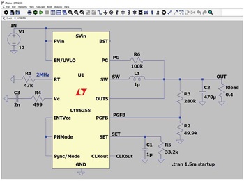
図3の回路において、出力電圧はSETピンに接続した抵抗を利用して設定します。ただ、出力電圧とPGFBピンの間には抵抗R2、R3から成る抵抗分圧器が存在します。この抵抗分圧器は、PGピンの機能を実現するためだけに使用されます。つまり、制御ループには影響を及ぼしません。この点には注意してください。
まとめ
従来、レギュレータの制御ループでは抵抗分圧器が一般的に使用されていました。これは十分に確立された手法です。それに対し、本稿ではユニティゲインのアーキテクチャという新たな手法を紹介しました。現在、この手法を採用する方向にレギュレータの設計は移行しつつあります。この進化の恩恵として、低周波数領域のノイズのレベルを非常に低く抑えられるようになります。最小限のノイズは生成されますが、それらは出力電圧の値には依存しません。そのこともあり、ユニティゲインのアーキテクチャを採用すれば、最小0Vまでの非常に低い電圧を生成することができます。アナログ・デバイセズは、この革新的な技術を採用したリニア・レギュレータとスイッチング・レギュレータを既に数多く提供しています。
