Digital Potentiometers Enable Fast, Linear Adjustment of Switched Mode Power Supplies
Digital Potentiometers Enable Fast, Linear Adjustment of Switched Mode Power Supplies
Apr 1 2015
The capability to finely adjust the output voltage in a power supply makes it is possible to remove tolerances and drops in the power path, verify the operation at the system limits, or implement simple dynamic voltage control for microprocessors. This article explores several options for adjusting a switched mode power supply (SMPS) and proposes a solution that uses a switching regulator with a digital potentiometer as the feedback control element, highlighting the design issues and the ways that they can be solved. Finally, the AD5141 single channel, nonvolatile digiPOT is presented as a simple way to overcome common limitations in this application.
Switched mode power supply regulators provide higher efficiency than linear regulators in high current systems, with typical efficiencies of greater than 90% for currents above 100 µA.
In a low dropout (LDO) regulator, the efficiency depends on the quiescent current (Iq) and the forward voltage drop, with higher quiescent current causing lower efficiency, as shown in Equation 1.
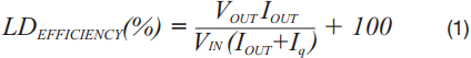
Today’s LDOs have reasonably low quiescent current, so Iq can be neglected if it is very small compared to ILOAD. Then, the LDO efficiency is simply (VOUT/VIN) × 100. Because the LDO has no way to store significant amounts of unused energy, power not delivered to the load is dissipated as heat within the LDO. Typical LDO efficiencies are less than 83%.
With their lower losses, switching regulators are replacing linear regulators in applications such as ATE, FPGAs, and instrumentation that require high current or dynamic loads.
It is often necessary for the system designer to adjust supply voltages, either to optimize their levels or to force them away from nominal values when characterizing system performance under extreme conditions. This function is typically performed during in-circuit test (ICT), when a manufacturer wants to guarantee that a product functions correctly at nominal supplies ± 10%, for example.
This procedure, called margining, is done by deliberately changing the supply voltage within the expected range. In addition, the capability to finely adjust the output voltage makes it possible to compensate for supply tolerance and voltage drops in the power path.
Other applications, such as dynamic voltage control for a microprocessor, must be able to change the voltage on-the-fly, reducing the voltage in low power modes and increasing it in high performance modes.
An SMPS works similarly to an LDO, as shown in Figure 1. The output voltage is compared with an internal reference, with the difference connected to the pulse width modulator.

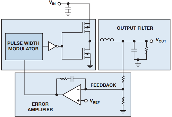
Figure 1. SMPS voltage control loop.
The pulse width modulator compares a ramp with the amplifier output, and generates the PWM signal that controls the switches that deliver energy to the load.
Adjusting the output voltage can be done by controlling the voltage at the inverting amplifier pin.
This can be done externally, using a DAC, or a digital potentiometer. Some regulators allow internal control of the feedback voltage using a serial interface such as PMBUS, I2C, or SPI. Table 1 compares all three methods in terms of adjustment capability and power dissipation.
| Method | Coarse Adjustment | Fine Adjustment | Power Supply Rails | Typical PowerConsumption |
| DAC | Meduim | High | VMIN < 2.5 V | >100 µA |
| digiPOT | High | Meduim | VMIN < 2.3 V | >20 µA |
| Internal Registers | High | Low | Not applicable | Low |
Some digital potentiometers are available with nonvolatile memory, so the output supply can be programmed in test. This easy to use feature provides a substantial benefit as compared to the other two methods.
Linearizing the Transfer Equation
Equation 2 describes the output voltage of the SMPS based on the ratio of feedback resistors R1 and R2,
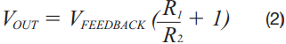
where VFEEDBACK is the internal reference voltage.
Before directly replacing R1 and R2 by a digital potentiometer, some issues should be considered. Internally the digital potentiometer has two resistor strings, RAW and RWB.
Both string resistors are complementary,

where RAB is the end-to-end resistance or nominal value.
Replacing R1 and R2 with RAW and RWB results in a logarithmic transfer function. The nonlinear relation between the digital code and the output voltage decreases the low end resolution. Figure 2 shows an example for a 16-tap digital potentiometer.


Figure 2. Logarithmic transfer function.
This problem can be overcome in several ways; the more common are to use the digital potentiometer in rheostat mode, or to place resistors in series with the potentiometer.
Minimizing the Tolerance
Due to the resistor tolerance, using a digital potentiometer in conjunction with external resistors can cause mismatch problems. Precision devices might have 1% resistor tolerance, but the vast majority of digital potentiometers can only achieve 20% resistor tolerance.
In this case, reducing the mismatch is possible by using a series/parallel resistance combination, as shown in Figure 3 and Figure 4. As a downside, the dynamic range is reduced as well.


Figure 3. Rheostat and serial resistor.


Figure 4. Potentiometer mode.
In rheostat mode, the series resistance must be high enough to render the tolerance of the digital potentiometer negligible, that is R2 ≥ 10 × RAB. In potentiometer mode, the parallel resistor must be small enough, that is ![]() .
.
Linearizing the potentiometer using a series-parallel combination could be quite complex, as shown in the equivalent circuit of Figure 5,

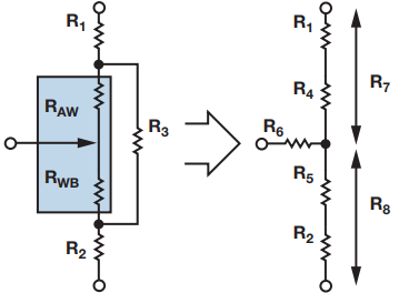
Figure 5. Final Y-∆ transform.
where:
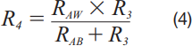
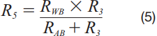
![]()
![]()
the feedback input pin typically has high impedance, so the effect of R6 can be made negligible.
Increasing the Bandwidth
The switching regulator operates at high frequency, typically above 1 MHz, allowing the use of small external components. In worst-case scenarios, it must power dynamic loads, so the feedback resistor network must provide enough bandwidth to accurately track the output voltage. Due to the parasitic internal switch capacitance, the digital potentiometer acts as a low-pass filter.
If the feedback network does not have enough bandwidth, the output voltage will oscillate, as shown in Figure 6.


Figure 6. Discrete feedback resistance vs. digital potentiometer with limited bandwidth.
A simple way to overcome this limitation is to place a capacitor in parallel between the output and the feedback network (as shown in Figure 7), reducing the high frequency impedance, and minimizing the oscillation time.


Figure 7. Parallel capacitor reduces high frequency impedance, minimizes oscillation.
A Simpler Solution Without Compromise
ADI’s new AD5141 digiPOT overcomes the problems presented by other digital potentiometers. Its patented linear gain setting mode allows independent control of each string resistor, so
![]()
enabling this mode, no external resistors are needed. The resistor tolerance becomes negligible, and the overall error of the transfer function is only due to the internal string mismatch, which is typically less than 1%.
Each string resistor has an associated EEPROM location, so an independent value for each string can be loaded upon power-up. In addition, the device provides up to 3 MHz bandwidth for a fast feedback loop as shown in Figure 8.

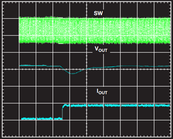
Figure 8. AD5141 (10 kΩ) version in linear gain setting mode.
Conclusion
Switched mode power supply regulators are commonly used in high current applications due to their high efficiency. This article describes several ways that can be used to digitally control the output voltage.
Due to the inherent benefits obtained by powering up a system in a predefined output state, a solution that uses digital potentiometers with internal nonvolatile memory is desirable. The main trade-offs faced by designers include providing enough resolution, accuracy, and bandwidth to achieve outstanding performance. The AD5141 digiPOT enables designers to provide an optimum solution without compromises.
About the Authors
Miguel Usach Merino received his degree in electronic engineering from the Universitat de Valencia. Miguel joined ADI in 2008 and works as an applications engineer in the Linear and Precision Technology Group in Valencia, ...
Related to this Article
Products
Product Categories
Latest Media 21


