Using the MAX6951/MAX6950 LED Display Drivers with SPI Interface to Communicate with the MAXQ2000 Microcontroller
Using the MAX6951/MAX6950 LED Display Drivers with SPI Interface to Communicate with the MAXQ2000 Microcontroller
Abstract
This application note describes assembly language techniques for the MAX6951/MAX6950 LED drivers using the MAXQ2000's SPI peripheral.
Introduction
The MAX6950 and MAX6951 are five-digit and eight-digit common-cathode LED display drivers controlled through a high-speed SPI interface. These devices employ a unique multiplexing scheme to minimize the connections between the LED driver and the LED panels. The MAXQ2000 is a high-performance 16-bit, RISC microcontroller with an integrated SPI module, which provides an easy interface between an LED driver and microcontroller. This application note gives a sample code in the MAXQ® assembly language that demonstrates how to use the MAXQ2000 SPI module to experiment with MAX6951/MAX6950 functions.
Hardware and Software Requirements
To perform the interface experiment described in this application note, you need the MAX6951 Evaluation Kit (EV kit), the MAXQ2000 Evaluation Kit (including MAX-IDE software), a +5V power supply with minimally 200mA capacity, and a PC with an available serial port.
Hardware Setup
- MAX6951 EV kit jumper settings
To disconnect signals active-low CS, DIN and SCLK from the level-translator chip on the EV kit, cut the traces connecting Pins 1 and 2 of JU2, JU3 and JU4. - MAXQ2000 EV kit jumper and DIP switch settings
Set switch SW3 1-8 to the off position.
JU1: connect Pins 1 and 2
JU2: connect Pins 1 and 2
JU3: connect Pins 1 and 2
JU4: open
JU10: open
JU11: on (The MAXQ2000 EV kit is powered by a JTAG interface board, which is powered by a +5V power supply.) - Connect the two EV kits as shown in Figure 1.
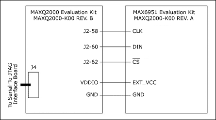
Figure 1. Schematic for the connection between the MAX6951 EV Kit and the MAXQ2000 EV Kit.
Firmware Description
The complete firmware files for this example project can be downloaded from the Analog website, and can be compiled using Analog's integrated development and debugging environment, MAX-IDE for the MAXQ family of microcontrollers.
Download: Complete Firmware (ZIP, 18.8k)
main.asm file
This file is the main demo loop for this example project. It calls different routines to demo the correct data writing to the MAX6951 registers. The firmware demonstrates the following MAX6951 functions in sequence:
- MAX6951 SPI interface initialization.
- In hexadecimal decode mode, the writing and displaying of 0, 1, 2, ..., A, B, C, D, E, F and 8 decimals (i.e., lighting all LED segments) to both the P0 plane and P1 plane of all the digits on the MAX6951.
- In no-decode mode, the writing and displaying of the above letters and other recognizable letters such as H, L, P, Q, Y, etc., with custom built-in fonts.
- LED dimming loop. This loop shows how to write to the MAX6951 intensity register to test the digital brightness control.
- Scan limit loop. This loop displays from one to eight digits with the same intensity settings.
Note: monitor the process to ensure that the brightness decreases when the scan limit increases. - Blinking loop, This loop writes a different digit number to plane P0 and plane P1 of every digit. It also uses a fast blinking mode to demonstrate segment-blinking control that can be synchronized across multiple LED drivers.
- Scrolling loop, This loop scrolls a text message, HELLO, from left to right and right to left.
- Bouncing loop, This loop bounces HELLO between the two LED edges.
- The counting loop. This last loop shows, in both hexadecimal decode mode and no-decode mode, how to design a display that counts how many milliseconds have elapsed.
max2000ev_6951.asm file
This file includes all the utility functions for communicating with the MAX6951 EV kit using the MAXQ2000 microcontroller. The major functions are:
- max6951_init: This function sets the MAXQ2000 in the correct SPI mode for talking to the MAX6951. It enables SPI and initializes the MAX6951 to display eight 0s on the display panel. Listing 1 shows this function in detail.
Listing 1. MAX6951 initialization code sample.
;******************************************************************************* ;* Function: max6951_init ;* ;* Sets the correct SPI modes for talking to the MAX6951, enables SPI, and ;* ;* initializes the MAX6951 to display 8 0s. ;* ;* Input: None. ;* ;* Output: None. ;* ;* Destroys: ACC, A[0] -- A[10], PSF ;* ;******************************************************************************* MAX6951_INIT: ; SET SPI BAUD RATE MOVE A[0], #2400H ; SYSTEM CLOCK IS 16,000,000 HZ MOVE A[1], #00F4H MOVE A[2], #4240H ; DESIRED BAUD RATE IS 1,000,000 HZ MOVE A[3], #000FH CALL SPI_SETBAUDRATE ; SET THE APPROPRIATE MODES FOR THE 6951 MOVE C, #SPI_IDLE_LOW ; IDLE = LOW CALL SPI_SETCLOCKPOLARITY MOVE C, #SPI_ACTIVE_EDGE ; ACTIVE = RISING EDGE CALL SPI_SETCLOCKPHASE MOVE C, #SPI_LENGTH_16 ; ALWAYS TRANSFER 16 BITS CALL SPI_SETCHARACTERLENGTH MOVE C, #SPI_MASTER_MODE ; MAXQ2000 IS THE MASTER, MAX6951 IS THE SLAVE CALL SPI_SETMODE ; ENABLE SPI MOVE C, #1 CALL SPI_ENABLE ; SHUTDOWN MAX6951 DISPLAY FIRST CALL MAX6951_SHUTDOWN ; SET MAX6951 IN HEXADECIMAL DECODE MODE MOVE ACC, #MAX6951REG_DECODE SLA4 SLA4 OR #0FFH ; HEXADECIMAL DECODE CALL MAX6951_TRANSMIT ; SET DISPLAY INTENSITY = 16/16 MOVE ACC, #MAX6951REG_INTENSITY SLA4 SLA4 OR #0FH ; INTENSITY = 16/16 CALL MAX6951_TRANSMIT ; SCAN LIMIT = 7 MOVE ACC, #MAX6951REG_SCANLIMIT SLA4 SLA4 OR #07H ; SCAN LIMIT = 7 CALL MAX6951_TRANSMIT RET - max6951_transmit: This function sends a register address and a data byte (16 bits) to the Max6951.
- max6951_set_all_n: These functions set both plane P0 and plane P1 of a digit register to number 'n'. All the functions have both hexadecimal decode and no decode versions.
- max6951_e_d_s_d: This function enables the MAX6951 display, then a half-second delay, shutdowns the display, and then delays for 100ms.
- max6951_screenshot: These functions put HELLO at eight different positions on the 8-digit LED panel.
- max6951_scroll_R_to_L: By displaying the screenshots in different sequences, this function scrolls HELLO from right to left in no-decode mode.
- max6951_scroll_L_to_R: By displaying the screenshots in different sequences, this function scrolls HELLO from left to right in no-decode mode.
- max6951_bouncing: This function bounces HELLO between the two LED edges.
- font_lookup: Given a digit value in hexadecimal format, this routine looks for the value that displays the same font in no-decode mode on a standard 7-segment LED.
- max6951_counting: This function counts and displays how many milliseconds have elapsed; the resolution is 10 milliseconds. Listing 2 shows the code in detail.
Listing 2. MAX6951 counting code sample.
;*******************************************************************************
;* Function:  max6951_counting
;*
;* This routine counts how many 10-milliseconds have elapsed and displays
;*
;* the value from 0000 to 9999 on LED digits 3-0(no way to blank leading digits).
;*
;  The routine displays the same value on LED digits 7-4(by using no decode
;*
;* mode, individual leading digits can be blanked).
;*
;* Input:     None
;*
;* Output:    None
;*
;* Destroys:  ACC, A[1] - A[4], A[9]
;*
;*******************************************************************************
MAX6951_COUNTING:
	CALL 	MAX6951_SHUTDOWN
	CALL	MAX6951_SET_ALL_0	; SET ALL BITS OF DATA REGISTERS TO 0
	MOVE   ACC, #010FH	; HEXDECIMAL DECODE DIGITS 3-0, NO DEOCDE DIGITS 7-4
	CALL	MAX6951_TRANSMIT
	; INITIALIZE THE COUNT TO 0
	MOVE	A[1], #0			; A[1] => DIGIT 0
	MOVE	A[2], #0			; A[2] => DIGIT 1
	MOVE	A[3], #0			; A[3] => DIGIT 2
	MOVE	A[4], #0			; A[4] => DIGIT 3

COUNT_LOOP:
INCREASE_DIGIT3:
	MOVE	ACC, A[4]			; PROCESS DIGIT 3
	SUB	#9
	JUMP	Z, INCREASE_DIGIT2		; DIGIT 3 = 9, THERE IS CARRY OVER
	MOVE	ACC, A[4]			; DIGIT 3 < 9, CONTINUE
	ADD	#1
	MOVE	A[4], ACC
	CALL	FONT_LOOKUP			; LOOK UP THE VALUE FOR THIS FONT
						; STORE IT IN A[9], KEEP ACC UNCHANGED
	OR	#6300H
	CALL	MAX6951_TRANSMIT 		; NO CARRY OVER, WRITE DIGIT 3 NEW VALUE
	MOVE	ACC, A[9]			; WRITE THE NO DECODE VALUE TO DIGIT 7
	OR     #6700H
	CALL	MAX6951_TRANSMIT
	JUMP	DISPLAY_NUMBER

INCREASE_DIGIT2:
	OR	#6300H
	CALL	MAX6951_TRANSMIT		; WRITE 0 TO DIGIT 3 REGISTER FIRST
	MOVE	A[4], #0			; SET DIGIT 3 BACK TO 0
	MOVE	ACC, #677EH			; NO DECODE VALUE FOR FONT '0' IS "7EH"
	CALL 	MAX6951_TRANSMIT 		; WRITE 7EH TO DIGIT 7 REGISTER

	MOVE	ACC, A[3]			; PROCESS DIGIT 2
	SUB	#9
	JUMP	Z, INCREASE_DIGIT1		; DIGIT 2 = 9, THERE IS CARRY OVER
	MOVE	ACC, A[3]			; DIGIT 2 < 9, CONTINUE
	ADD	#1
	MOVE	A[3], ACC
	CALL	FONT_LOOKUP			; LOOK UP THE VALUE FOR THIS FONT
						; STORE IT IN A[9], KEEP ACC UNCHANGED
	OR	#6200H
	CALL	MAX6951_TRANSMIT		; NO CARRY OVER, WRITE DIGIT 2 NEW VALUE
	MOVE	ACC, A[9]			; WRITE THE NO DECODE VALUE TO DIGIT 6
	OR     #6600H
	CALL	MAX6951_TRANSMIT
	JUMP	DISPLAY_NUMBER

INCREASE_DIGIT1:
	OR	#6200H
	CALL	MAX6951_TRANSMIT		; WRITE 0 TO DIGIT 2 REGISTER FIRST
	MOVE	A[3], #0			; SET DIGIT 2 BACK TO 0
	MOVE	ACC, #667EH			; NO DECODE VALUE FOR FONT '0' IS "7EH"
	CALL 	MAX6951_TRANSMIT 		; WRITE 7EH TO DIGIT 6 REGISTER

	MOVE	ACC, A[2]			; PROCESS DIGIT 1
	SUB	#9
	JUMP	Z, INCREASE_DIGIT0		; DIGIT 1 = 9, THERE IS CARRY OVER
	MOVE	ACC, A[2]			; DIGIT 1 < 9, CONTINUE
	ADD	#1
	MOVE	A[2], ACC
	CALL	FONT_LOOKUP			; LOOK UP THE VALUE FOR THIS FONT
						; STORE IT IN A[9], KEEP ACC UNCHANGED
	OR	#6100H
	CALL	MAX6951_TRANSMIT		; NO CARRY OVER, WRITE DIGIT 1 NEW VALUE
	MOVE	ACC, A[9]			; WRITE THE NO DECODE VALUE TO DIGIT 5
	OR     #6500H
	CALL	MAX6951_TRANSMIT
	JUMP	DISPLAY_NUMBER

INCREASE_DIGIT0:
	OR	#6100H
	CALL	MAX6951_TRANSMIT		; WRITE 0 TO DIGIT 1 REGISTER FIRST
	MOVE	A[2], #0			; SET DIGIT 1 BACK TO 0
	MOVE	ACC, #657EH			; NO DECODE VALUE FOR FONT '0' IS "7EH"
	CALL 	MAX6951_TRANSMIT 		; WIRTE 7EH TO DIGIT 5 REGISTER

	MOVE	ACC, A[1]			; PROCESS DIGIT 0
	SUB	#9
	JUMP	Z, COUNT_COMPLETE		; DIGIT 0 = 9, COUNTING IS OVER
	MOVE	ACC, A[1]			; DIGIT 0 < 9, CONTINUE
	ADD	#1
	MOVE	A[1], ACC
	CALL	FONT_LOOKUP			; LOOK UP THE VALUE FOR THIS FONT
						; STORE IT IN A[9], KEEP ACC UNCHANGED
	OR	#6000H
	CALL	MAX6951_TRANSMIT		; NO CARRY OVER, WRITE DIGIT 0 NEW VALUE
	MOVE	ACC, A[9]			; WRITE THE NO DECODE VALUE TO DIGIT 4
	OR     #6400H
	CALL	MAX6951_TRANSMIT

DISPLAY_NUMBER:		; DISPLAY DIGIT 3-0 IN HEXADECIMAL DECODE MODE
				; DIEPLAY DIGIT 7-4 IN NO DECODE MODE
	CALL	MAX6951_ENABLE
	CALL	MAX6951_10MS_DELAY
	JUMP 	COUNT_LOOP

COUNT_COMPLETE:
	RET
maxq2000_spi.asm file: This file is the utility function for configuring and using the MAXQ2000's SPI module. The file is integrated in the MAX-IDE; the user can use it without modification.
divide32.asm file: This is a 32-/32-bit divide routine provided in the MAX-IDE software.
maxq2000.inc, maxq2000_spi.inc, and max2000ev_6951.inc files: These are include files for MAXQ2000 pin definitions and MAX6951 register definitions.
Conclusion
The MAX6951/MAX6950 SPI LED drivers are easy-to-use common-cathode display drivers that interface to microcontrollers through an SPI serial interface. The MAXQ family of microcontrollers provides a convenient integrated SPI module that communicates to LED drivers with SPI interfaces. The sample code presented here helps a user understand how to exercise MAX6951 LED features. The sample code can also be utilized in similar MAXQ2000-based application development.