AN-1567: Smoke Testing with the ADPD188BI Optical Smoke and Aerosol Detection Module
Introduction
Smoke detectors have historically been built using ionization alarms. However, there is a move towards photoelectric smoke alarms. Ionization alarms detect fast flaming fires more quickly than a photoelectric smoke alarm, typically 30 sec to 90 sec faster. This difference in detection speeds is because of the time delay while the smoke diffuses into the smoke chamber. However, the photoelectric smoke alarm responds much more quickly to smoldering fires, typically 10 min to 50 min faster. The photoelectric smoke alarm is also less susceptible to nuisance alarms such as alarms from burnt toast or shower steam. The Underwriters Laboratory (UL) is releasing a new version of the UL-217 and UL-268 standards in 2020, which all smoke alarms in North America must pass. Commercial and residential smoke detectors are being redesigned to meet these new standards.
Photoelectric smoke alarms use multiple wavelengths, which allows particle size differentiation. Using multiple wavelengths enables the smoke alarm to differentiate between different types of smokes and common nuisance sources, improving the ability for the smoke alarm to reject nuisance sources and to avoid false alarms.
The ADPD188BI is a complete photometric system for smoke detection using optical dual wavelength technology. The module integrates a highly efficient photometric front end, blue and infrared (IR) light emitting diodes (LEDs), and a photodiode (PD). These items are housed in a custom package that prevents light from going directly from the LED to the photodiode without first entering the smoke detection chamber.
This application note describes the testing of the ADPD188BI against all of the UL-217 and UL-268 tests required for UL certification of a smoke detector, as well as the EN-54 dazzle test.

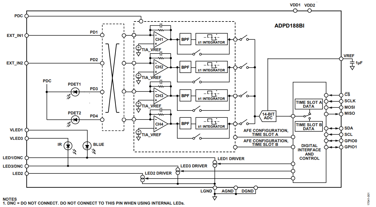
Figure 1. ADPD188BI Block Diagram.
UL Testing
The ADPD188BI was evaluated against the full suite of smoke tests listed in the UL-217 Ed. 8 smoke detector specification. Any smoke detector sold in North America must pass these tests for UL certification. By characterizing the response of the system to these smoke sources, these tests provide an indication to the smoke detector manufacturer of the expected performance of the final smoke detector design using the ADPD188BI, and provide guidance for classification and threshold setting algorithms.
Hardware
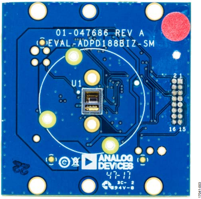
The test hardware used for UL testing was the EVAL-ADPD188BI-SK evaluation board controlled by an EVAL-ADPDUCZ microcontroller board. A simplified schematic of the EVAL-ADPD188BI-SK circuit is shown in Figure 2, and a picture of the board is shown in Figure 3.

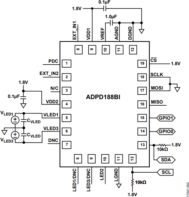
Figure 2. EVAL-ADPD188BI-SK Simplified Schematic.

The smoke response data presented in this document was collected using the evaluation board without any enclosure or smoke chamber to best represent the performance capabilities of the sensor.
UL Tests Conducted
The ADPD188BI optical module was subjected to the tests shown in Table 1.
| Test | Standard | Section |
| Paper Fire | UL217 | Paragraph 51.2 |
| Wood Fire | UL217 | Paragraph 51.3 |
| Flaming Polyurethane Foam | UL217 | Paragraph 51.4 |
| Smoldering Smoke | UL217 | Paragraph 52 |
| Smoldering Polyurethane Foam | UL217 | Paragraph 53 |
| Cooking Nuisance Smoke | UL217 | Paragraph 54 |
| Dust | UL217 | Paragraph 68 |
| Dazzling | EN14604 (European standard) | Clause 5.6 |
All tests were conducted at Underwriters Laboratories in Deerfield, Illinois. The tests were operated and reference data gathered by UL personnel. All ADPD188BI hardware and software was maintained and operated by Analog Devices, Inc., personnel.
Inside the UL test chamber, the smoke obscuration level at each smoke alarm location is monitored by a photocell light beam assembly mounted adjacent to the smoke detector test site, at a predetermined distance from the smoke source, defined by the UL test being conducted. The UL reference light beam measures smoke obscuration level vs. time, expressed in percent obscuration per foot. The beam data is collected and time tagged for correlation with the ADPD188BI sensor data.
Presentation of Results
The smoke response for the blue and IR channels of the ADPD188BI is expressed by the power transfer ratio (PTR) in units of nW of optical power returned to the photodiode per mW of optical power emitted by the LED. Expressing the smoke response in this way allows a common unit of measurement, independent of analog front-end (AFE) configuration, for different optical systems and different settings within a system. It also allows a meaningful comparison of different types of smoke.
The conversion from PTR to actual code counts expected from the system is a function of the specific AFE settings, including gain, number of pulses, and LED current. The ADPD188BI AFE allows great flexibility for the system designer to adjust these settings to trade off key system parameters such as average power consumption, ambient light rejection, and signal-tonoise ratio (SNR). For any given settings, the expected output of the system for each smoke type can be calculated.
Test Results
Each of the UL tests for the different types of smokes have limits to where an alarm must be triggered. Some tests (for example, the smoldering polyurethane test) require that an alarm be set prior to some level of obscuration. Other tests (for example, the flaming wood test) require that an alarm occurs prior to a time limit following ignition. These limits are shown in Table 2.
| Fire Condition | Alarm Time Specification | Alarm Obscuration Specification |
| Wood Fire | Less than 4 min into test profile | Not applicable |
| Paper Fire | Less than 4 min into test profile | Not applicable |
| Polyurethane Fire | Less than 4 min into test profile | Before 5% per foot |
| Smoldering Polyurethane | Not applicable | Before 5% per foot |
| Smoldering Wood | Not applicable | Before 5% per foot |
| Hamburger Nuisance Test | Not applicable | Not before 1.5% per foot |
Data was collected for each test, and plots were generated by time aligning the reference beam response with the blue and IR response of the ADPD188BI. In all tests, the ADPD188BI response tracked the reference data very well, demonstrating the ability of the sensor to detect all of the smokes in the UL217 suite of tests.
Figure 4 shows an example for the flaming polyurethane test. In this example, the white trace is the response of the reference beam, and it is expressed in percent obscuration per foot on the right y-axis. The blue trace is the response to the blue LED. The red trace is the response to the IR LED. Both the blue and IR responses are expressed as PTR in nW per mW on the left y-axis. The reference beam response shows how the obscuration level changes as a function of time. The responses of the blue and IR show what the power transfer ratio is for different types of smoke at different levels of obscuration, and allows the user to determine what LED power level must be set to trigger an alarm at a specific threshold level based on type of smoke being detected.

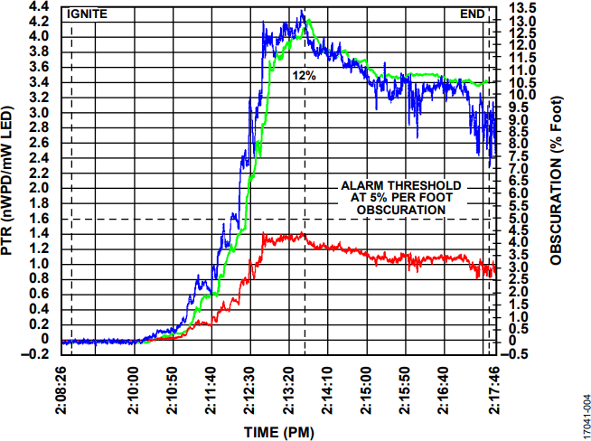
Figure 4. Response Plot for Flaming Polyurethane Test.
The UL specification for the flaming polyurethane test requires that the alarm must be triggered before there is 5% obscuration per foot and less than 4 min into the test profile. The result shown in Figure 4 shows that the reference beam reaches the 5% obscuration per foot threshold prior to the four minute mark. To set an alarm threshold for the ADPD188BI, a level must be selected prior to 5% obscuration per foot. From the data shown in Figure 4, an alarm threshold for blue can be set at approximately 2 nW/mW, and the IR at approximately 0.8 nW/mW. Margin must be added to these threshold levels in the final application as appropriate to suit the smoke detection algorithm.
Interpreting the Test Results
Figure 5 and Figure 6 show the blue and IR responses to the UL217 smoke tests at the rated obscuration and/or time thresholds (see Table 2). In Figure 5 and Figure 6, the unfilled portion of each bar represents the levels as measured. In the filled portion of the bar, thresholds are reduced to provide an additional 20% margin of error for detection. For the hamburger nuisance test, the filled portion of the bar shows a threshold increased to provide an additional 20% margin of error to not detect.
Figure 7 shows the ratio of the blue response to the IR response for the various smoke tests. The blue/IR ratio increases as the particle size gets smaller below approximately 1 μm. This ratio can be used by a detection algorithm, along with absolute power levels and temporal response, to better differentiate between smoke and nuisance sources.
The data in Figure 5 and Figure 6 shows that the threshold for a valid smoke alarm must be set based on the sensitivity of the flaming polyurethane test that has the lowest PTR, and therefore the least response of all the smoke sources tested. The hamburger nuisance test defines the low end of sensitivity to prevent false alarms. Every other type of smoke has a significantly higher response relative to the flaming polyurethane. If a threshold is set appropriately to trigger an alarm on flaming polyurethane, the smoke detector also triggers an alarm for all other valid types of smoke defined in the UL217 standard. For the higher responding smokes such as the smoldering polyurethane or flaming wood, the alarming sensitivity levels exceeds the UL217 requirement by a wide margin. Data from the two smoke box tests shown in Figure 5 and Figure 6 are included as a reference only. These tests are not representative of real world smoke detection scenarios and is not included in any threshold setting process. UL217 does not specify an absolute detection requirement for these tests.

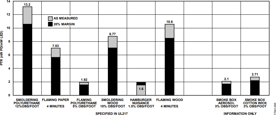
Figure 5. Blue Channel Signal Response to the UL217 Smoke Tests.

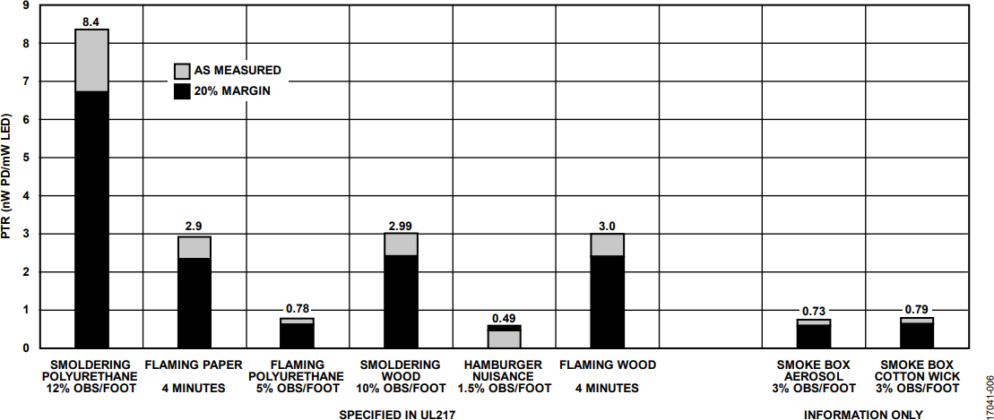
Figure 6. IR Channel Signal Response to the UL217 Smoke Tests.

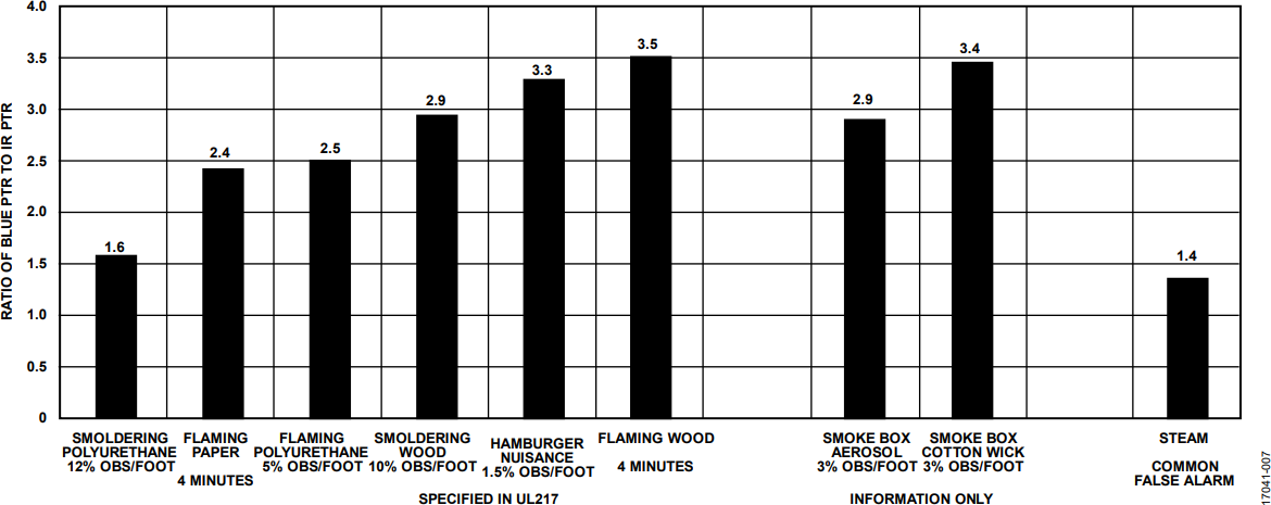
Figure 7. Ratio of the Blue/IR Response.
Dealing with Nuisance Sources
The new UL217 standard includes a specification for prevention of false alarms due to nuisance sources. This test is the cooking nuisance smoke test and is defined in Section 54 of the specification. In this test, a hamburger is burned in an oven to produce smoke. The smoke alarm is not allowed to trigger until after the smoke reaches 1.5% obscuration per foot.
As shown in Figure 5 and Figure 6, the level at which the alarm is not allowed to trigger as defined by the cooking nuisance smoke test overlaps with the level at which an alarm must trigger for the flaming polyurethane smoke test, especially after margin is added into the PTR threshold. Due to the overlap in sensitivities to these two tests, another level of intelligence must be added to the algorithm to differentiate between the flaming polyurethane smoke test and the cooking nuisance smoke test. Also, the data from the blue/IR ratios shown in Figure 7 shows that the ratio of the cooking nuisance smoke test is within the range of other valid types of smoke. Therefore, the ratio information also can not be used, on its own, to differentiate cooking nuisance smoke.
Figure 8 shows the responses of the flaming polyurethane and cooking nuisance tests vs. time. This plot shows that the alarm threshold for the flaming polyurethane test is reached much faster (approximately 3.5 min) than the obscuration level required for alarm on the cooking nuisance test (approximately 16.5 min). A smoke alarm algorithm can use this temporal information to differentiate between the smoke from flaming polyurethane and the cooking smoke to make a final determination whether to trigger an alarm or not.

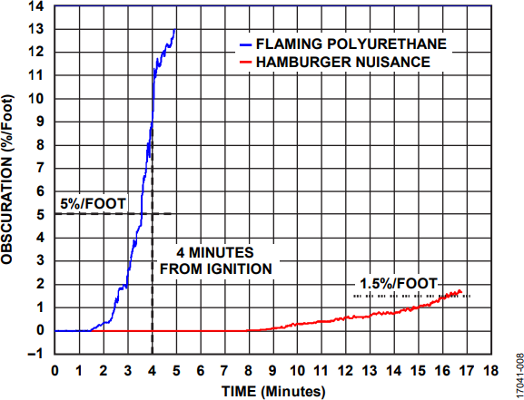
Figure 8. Temporal Response of Flaming Polyurethane Test and Cooking Nuisance Smoke Test.
A similar issue arises when a smoke alarm must differentiate between a nuisance source such as steam from a valid smoke. Historically, this issue is a problem for smoke alarms placed outside of bathrooms. False alarms can be triggered by the steam from a shower.
Using the ratio information from the two wavelengths of the ADPD188BI, Figure 7 shows that steam is a large particle compared to most types of smoke and, therefore, the ratio information can be used as a reliable discriminant between steam and these smokes. However, the ratio for the steam is relatively close to the ratio for the smoldering polyurethane test, so it may not be possible to differentiate steam from smoldering polyurethane smoke based on ratio alone.
Similar to the flaming polyurethane smoke vs. cooking nuisance smoke, the obscuration levels at which an alarm is triggered for smoldering polyurethane vs. steam occur over significantly different time scales. The obscuration alarm threshold for smoldering polyurethane of 12%/ft takes approximately 30 min to achieve where a similar level of obscuration due to steam is achieved on the order of 5 to 10 times faster.
Dazzling Test from the European Standard (EN14604)
Several smoke detector manufacturers are actively developing chamberless smoke detectors. These chamberless smoke detectors eliminate the smoke chamber and expose the optics to the external environment. A chamberless smoke detector is able to trigger alarms faster than a chambered design and also simplifies the design of the smoke detector, as well as reduces cost. One of the biggest challenges to this type of design is the ability of the optics to reject ambient light sources.
The object of the dazzling test is to show that the sensitivity of the smoke alarm is not unduly influenced by the close proximity of artificial light sources. This test is only applied to photoelectric smoke alarms, because ionization chamber smoke alarms are considered unlikely to be influenced.
The dazzling test places the smoke sensor inside a box that is approximately 38 cm per side. Two of the sides are open to allow the flow of smoke. Circular fluorescent lamps are mounted to the remaining four sides of the box. Refer to EN-14604 Annex D for a complete mechanical description of the apparatus.
The test exposes the smoke detector to bright fluorescent light from all sides. The specification states that, in the presence of the fluorescent lights, the smoke detector must not trigger false alarms and the sensitivity must not change beyond 60%. The test procedure is as follows:
- The test aerosol is ramped from 0%/ft to 4.2%/ft obscuration.
- The responsivity is measured with the lights off.
- The chamber is cleared.
- The lamps are cycled 10 sec on and 10 sec off, 10 times.
- The lamps are then turned on for at least 1 min.
- The test aerosol is ramped again as in Step 1, and the responsivity is measured with the lamps on.
- Lamps are turned off, and the chamber is cleared.
Under these test conditions, the ADPD188BI showed a 7% change in sensitivity on the blue channel and a 3% change in sensitivity on the IR channel in the light on vs. light off condition. This is well within the test limit of 60% set by the EN specification.

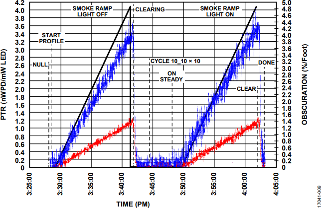
Figure 9. Test Results for the Dazzling Test.
Conclusions
The ADPD188BI is an optical module utilizing dual wavelength technology for optical smoke and aerosol detection. The device was tested at the Underwriters Laboratory against the UL217 standard for certification of smoke detectors. The data and results shown in this application note show that a smoke detector that uses the ADPD188BI has the required performance to pass the UL217 standard.
With the excellent light rejection of the ADPD1080 analog front end that is integrated in the ADPD188BI module, the EN14604 dazzling test is passed, enabling the design of lower cost chamberless smoke detectors.
Author
