AN-1360: How the ADGM1304 and ADGM1004 Increase Test Instrumentation Channel Density and Test Functionality
Introduction
This application note discusses the ADGM1304 and ADGM1004 microelectromechanical system (MEMS) switches and the positive effects these switches have in test equipment applications, specifically in automatic test equipment (ATE) applications. The size advantage, wideband radio frequency (RF) performance, precision dc/0 Hz performance, and mechanical lifetime advantages offered by the MEMS switches vs. RF relays are important in ATE applications.
Typical signal chains and block diagrams show where the MEMS switches can be used and where the switches add value in comparison to commonly used RF relays, in terms of reduced board area usage and performance improvements. This application note also discusses and compares the performance of a typical relay used in test equipment to the performance of the MEMS switch.
Switching in Test Instrumentation
Background
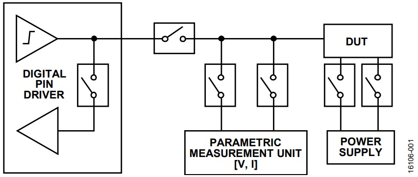
Switching functionality is a basic and critical function in all electronic test instrumentation. Due to increasing device under test (DUT) complexity and increasing channel/pin numbers and functions, the type of testing and the number of tests required has also increased. DC voltage and current precision performance testing, mixed-signal testing, high frequency digital testing, and RF testing can all be used for a single device evaluation, often in parallel to one another. With hundreds of tests required per device evaluation, especially in automatic testing equipment (ATE), the test speed is important. The complexity in test type and signals used affects the test hardware architecture and its associated switching functionality. In the case of ATE test instrumentation, a high level block diagram of a typical tester setup is shown in Figure 1. It is common to see the digital pin driver, parametric measurement unit (PMU), and power supplies with the associated switching integrated into a single instrument test card inside the ATE tester.

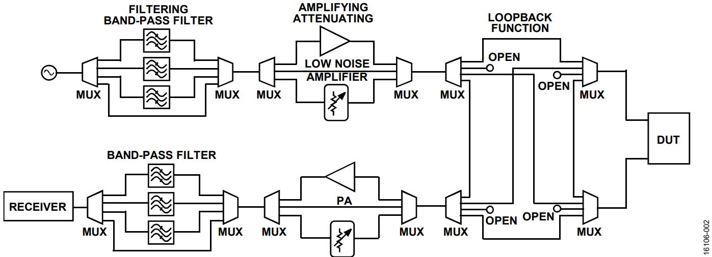
Ancillary switching functions can also be needed outside the tester, particularly on the device interface board (DIB), which is sometimes called the test interface unit (TIU). Figure 2 shows an example of this type of functionality and switching for an ac/RF test setup at the DUT. Signal filtering, amplification, and calibration paths are often required on the DUT test board to provide enough test flexibility to improve the test system performance, for example, to minimize the noise floor and enable the subtraction of printed circuit board (PCB) losses.

The type of switches used depends on the type of signal and performance required. Complementary metal-oxide semiconductor (CMOS) switches, photoMOS switches, reed relays, electromechanical relay (EMR) switches, gallium arsenide (GaAs) and silicon on insulator (SOI)-based RF switches are used in modern test equipment and device TIU boards.
Many high performance, solid state switches are used in ATE test equipment; however, large EMRs are still used when dc PMU signals and high speed digital/RF signals need to be carried on a common test path with minimal signal loss and distortion. These testing requirements are common when testing high performance electronic devices. An RF or high speed digital device often undergoes a large number of precision voltage and current dc-based tests, high speed digital interface testing, and RF signal transmit/receive testing. The precision PMU-based testing is typically for DUT leakage characterization and is an important screen for device performance in conjunction with high speed measurements. Precision testing and high speed testing requirements typically drives the need for high performance EMR usage.
EMRs can have some limitations. They are large, slow to actuate, have very limited cycle lifetimes, are difficult to design onto a PCB from a routing perspective, require external, high power driver circuits, and are cumbersome to rework. Unless very large, coaxial connector type, modular form factor EMRs are used, the bandwidth is limited and can greatly restrict the realizable system performance and system channel count.
MEMS Switch Advantage
MEMS Technology
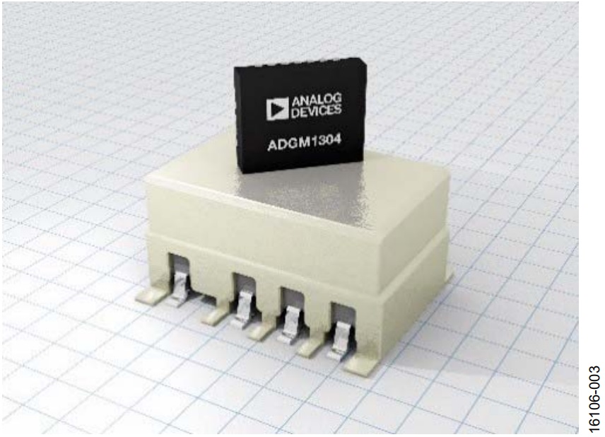
The Analog Devices, Inc., MEMS switches combine the benefits of EMRs in a significantly smaller form factor with increased RF and cycle lifetime performance ratings. For a detailed discussion on MEMS switch technology, see the Technical Article, The Fundamentals of Analog Devices’ Revolutionary MEMS Switch Technology. In the case of test instrumentation, switch size is very important and can dictate functionality and the channel count that can be achieved on the tester instrument board or DUT interface TIU board. Figure 3 shows the ADGM1304 0 Hz/dc to 14 GHz, single-pole, four-throw (SP4T) MEMS switch sitting on top of a typical 3 GHz bandwidth, double-pole, double throw (DPDT) EMR. The achievable size reduction can be over 90% with respect to volume differences.

In addition to the physical size advantages of the MEMS technology, the electrical and mechanical performance of the switch is highly advantageous. Table 1 shows some of the key specifications for the ADGM1304 and ADGM1004 devices compared to a typical, higher frequency, single-pole, double throw (SPDT) 8 GHz EMR. The ADGM1304 and ADGM1004 devices have excellent bandwidth, insertion loss, and switching time, and have cycle lifetimes of 1 billion cycles. The higher bandwidth is key to driving the switch into new application spaces. The low power, low voltage, power supply integrated driver is another key advantage of the MEMS switch. The ADGM1004 has a high electrostatic discharge (ESD) rating of 2.5 kV human body model (HBM) and 1.25 kV field induced charged device model (FICDM), which further enhances ease of use.
| Switch Parameter | ADGM1304 MEMS | ADGM1004 MEMS | 8 GHz EMR (Typical) |
| Switch Configuration | SP4T | SP4T | SPDT (1 Form C) |
| Operational Frequency (3 dB) | 0 Hz/dc to 14 GHz | 0 Hz/dc to 13 GHz | 0 Hz (dc) to 8 GHz |
| LFCSP Size | 4 mm × 5 mm × 0.95 mm | 4 mm × 5 mm × 1.45 mm | 8.0 mm × 9.4 mm (TO-5) |
| On Resistance (RON) | 1.6 Ω (typical) | 1.8 Ω (typical) | 0.15 Ω (maximum) |
| On Leakage | 5 nA | 5 nA | 5 nA |
| Actuation Lifetime | 1 billion cycles (minimum) | 1 billion cycles (minimum) | 10 million cycles (typical) |
| Switching Speed | 30 μs (typical) | 30 μs (typical) | 4 ms (maximum) |
| Power Supply | 3.3 V (10 mW = 3.3 V x 2.9 mA), integrated driver | 3.3 V (10 mW = 3.3 V x 2.9 mA), integrated driver | 5 V (280 mW), external driver required |
| Insertion Loss (IL) | 0.4 dB (typical) at 6 GHz | 0.6 dB (typical) at 6 GHz | 0.8 dB (typical) at 6 GHz |
| Off Isolation | 24 dB (typical) at 2.5 GHz | 24 dB (typical) at 2.5 GHz | 27 dB (typical) at 3.0 GHz |
| Power Rating | 36 dBm, ±6 V dc | 32 dBm, ±6 V dc | 1 Amp/28 V dc |
| ESD Rating, RF Ports (HBM; FICDM) | 100V; 500V | 2.5 kV; 1.25 kV | Not specified |
Figure 4 shows the insertion loss and off isolation of the ADGM1304 SP4T MEMS switch compared to a popular DPDT 3 GHz EMR that is commonly used in test instrumentation. Figure 4 shows the signal bandwidth advantage of the MEMS switch over the EMR.


MEMS Switch Application Examples
Traditionally, EMR switches are necessary to enable dc/RF switching functions in ATE testers; however, using relays can restrict system performance due to the following issues:
- The large size of relay switches and keep out area design rules mean substantial area usage and lack of test scalability.
- Limited relay cycle lifetimes, in the millions of cycles.
- Having to cascade multiple relays together to achieve a desired switching configuration (for example, an SP4T configuration requiring three SPDT relays).
- PCB assembly issues when using relays often yield a high PCB rework rate.
- Achieving full bandwidth performance can be very challenging due to routing restrictions and relay performance limitations.
- Slow relay actuation speeds, in the millisecond time scales, limit the speed of testing.
Figure 5 to Figure 7 illustrate how MEMS switches can address these limitations and enhance value in ATE applications. Typical dc/RF switched fanout application schematics using EMR switches and the same application using the ADGM1304 or ADGM1004 MEMS switches are shown in Figure 5 and Figure 6. Figure 7 shows a photograph of a visual demonstration PCB realizing these two schematics. A fanout 16:1 multiplexing function is used in this demonstration. The relays in Figure 5 are DPDT EMR relays. Nine DPDT relays and a relay driver IC are needed to realize an 18:1 multiplexing function (eight DPDT relays only yield a 14:1 multiplexing function). The physical relay solution is shown on the left-hand side of Figure 7 and shows how large in area the relay solution is, how difficult it is to maintain symmetry between routing connections, and the need for a driver IC.

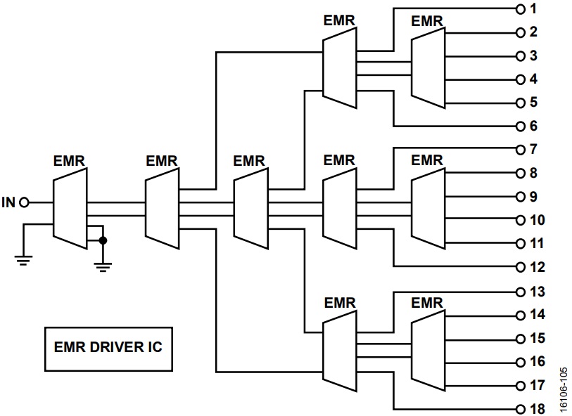
Figure 6 and the right-hand side of Figure 7 show the same fanout switching function, simplified by using only five ADGM1304 or ADGM1004 SP4T MEMS switches. The reduction in PCB area and routing complexity for the switching function is shown in Figure 6 and the right-hand side of Figure 7. In terms of x-y area, the reduction can be more than 68%, and in terms of volume, a reduction of more than 95% is possible. The ADGM1304 and ADGM1004 MEMS switches have built in low voltage, independently controllable switch drivers; therefore, no external driver IC is required. Due to the small package height of the MEMS switches (0.95 mm for the ADGM1304 and 1.45 mm for the ADGM1004), the switches can be mounted on the reverse side of a PCB. The small package height further enhances the achievable channel density.

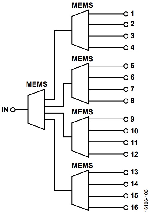

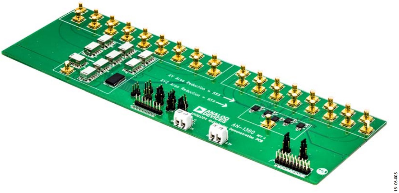
Figure 8 shows another test equipment switching use example. This figure shows a typical schematic of a test interface to a high speed or RF DUT using EMRs for the switching elements. In this case, both high speed RF signals and digital/dc signals are required to evaluate the electronic device.

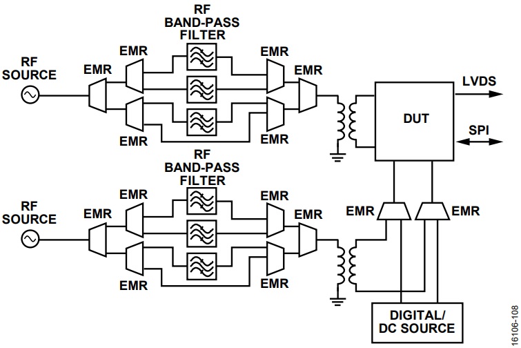
The Figure 8 solution uses relays as the switching solution. 14 SPDT relays are needed to enable the band-pass filter selection, digital signal routing, and dc parametric test functionality. Cascading of relays is required.
The equivalent solution using MEMS switches is shown in Figure 9. Figure 9 demonstrates the simplified and functionally enhanced test interface design when using MEMS switches. Only six ADGM1304/ADGM1004 switches are required for this design,

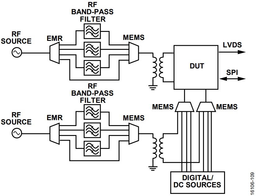
which significantly reduces the routing complexity and board area. The SP4T configuration of the ADGM1304 or ADGM1004 switches yields more functional channels overall with more digital and dc parametric test functions possible: eight with MEMS switches vs. four when using relays. The wide 14 GHz bandwidth, 0 Hz/dc operation, small package size, and low voltage control of the MEMS switches enable a much more flexible, longer cycle lifetime, smaller area switch solution that is capable of simultaneous high precision, high speed, digital signal routing, and wide bandwidth RF signal routing.
Summary
Increased device complexity and test requirements make ATE solutions difficult to realize in terms of optimal performance and space efficiencies. Switches are an integral part of any ATE test solution, with dc/digital and RF functionality now a common requirement. The Analog Devices MEMS switch technology is uniquely placed to enable increased test functionality and performance and use a smaller PCB area compared to traditional RF relay solutions. The ADGM1304 and ADGM1004 SP4T MEMS switches offer precision dc performance and wideband RF performance in a small SMD package with low drive power requirements, long cycle lifetimes, and enhanced ESD robustness. These features make the Analog Devices MEMS switch technology an ideal universal switching solution for all modern ATE equipment.
References
Analog Devices Makes MEMS Switch Technology a Commercial Reality. Analog Devices Product Highlight. 2017.
Carty, Eric. Fundamentals of ADI’s new RF MEMS Switch Technology. Video. Analog Devices. 2016.
Carty, Eric and McDaid, Padraig. Groundbreaking 5 kV ESD MEMS Switch Technology. Technical Article. Analog Devices. 2017.
Carty, Eric, Fitzgerald, Padraig, and McDaid, Padraig. The Fundamentals of Analog Devices’ Revolutionary MEMS Switch Technology. Technical Article. Analog Devices. 2016.
Author
