Objective
The objective of this lab activity is to reinforce the basic principles of CMOS logic from the previous lab activity titled “ADALM2000 Activity: Build CMOS Logic Functions Using the CD4007 Array” and to gain additional experience with complex CMOS gates. Specifically, you will learn how to combine CMOS transmission gates and CMOS inverters to build a D-type flip-flop or latch.
Background
To construct the logic functions in this lab activity, you will be using the CD4007 CMOS array and discrete NMOS and PMOS transistors (ZVN2110A NMOS and ZVP2110A PMOS) from the ADALP2000 analog parts kit. The CD4007 consists of three pairs of complementary MOSFETs, as shown in Figure 1. Each pair shares a common gate (pins 6, 3, and 10). The substrates of all PMOSFETs are common (positive supply Pin 14), as well as those of the NMOSFETs (ground Pin 7). For the left pair, the NMOS source terminal is tied to the NMOS substrate (Pin 7), and the PMOS source terminal is tied to the PMOS substrate (Pin 14). The other two pairs are more general-purpose. For the right pair, the drain terminal of the NMOS is tied to the drain terminal of the PMOS on Pin 12.


The CD4007 is a versatile IC with many uses, as we saw in the previous lab activity. For example, a single CD4007 can be used to make a chain of three inverters, an inverter plus two transmission gates, or other complex logic functions such as NAND and NOR gates. Inverters and transmission gates are particularly useful for building D-type latches or main/node flip-flops.
Static Discharge
The CD4007, like many CMOS integrated circuits, is easily damaged by static discharge. The CD4007 includes diodes to protect it from static discharge, but it can still be damaged if it is not handled carefully. Normally, one would use antistatic mats and wrist straps when working with static sensitive electronics. However, you may not have those when working at home outside a formal lab environment. A low budget way to avoid static discharge is to ground yourself before touching an IC. Discharging any built-up static charge before handling a CD4007 will help ensure that you do not have a broken chip halfway through the lab.
Materials
- ADALM2000 Active Learning Module
- Solderless breadboard
- One CD4007 (CMOS array)
- Two ZVN2110A NMOS transistors
- Two ZVP2110A PMOS transistors
Directions
We will now combine the double transmission gate built with the inverter chain of the previous exercise to build a D-latch as shown in Figure 2. The two transmission gates work in tandem to realize the D-latch. During the transparent phase of the latch, when CLK = 0, the first transmission gate (left) is on while the second (right) is off. D is transmitted to the output (Q) through the first transmission gate and the two series connected inverters. During the latched phase of the latch, when CLK = 1, the first transmission gate is off but the second transmission gate is on. As a result, any change in the Input D is not reflected at the Output Q. However, the second transmission gate, which is now turned on, ensures that the previous logic level at Q is retained through the closed positive feedback loop formed around the two inverters in series. Build the D-latch circuit shown in Figure 2 on your solderless breadboard. Use the CD4007 CMOS array for devices M1 to M6 and one ZVN2110A NMOS and ZVP2110A PMOS for each of the two inverter stages: the M7 and M8 stage and the M9 and M10 stage. Use the fixed 5 V power supply from the ADALM2000 to power your circuit.


Hardware Setup
Configure both AWG outputs as DC sources for the first steps of the lab. The scope channels are to be used to monitor the inputs and outputs of the circuit as needed. The fixed 5 V power supply is to be used to power your circuit. The fixed –5 V supply should be disabled during this lab.


Procedure
Connect pins 1 and 9, which serve as the D input of the latch to the output of AWG1. Connect pins 4 and 11, which serve as the Q output of the latch to Scope Channel 2. Connect Pin 6, which serves as CLK to AWG2. Be sure to turn on the fixed 5 V power supply.
First, apply logic low to CLK by opening the AWG control screen and setting AWG2 to 0 V DC. Apply logic high to the D input by setting AWG1 to 5 V DC.
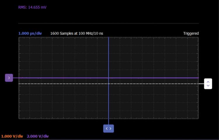
Observe the Output Q of the latch on Scope Channel 2. A steady 5 V should appear on the scope screen. Capture a screenshot.


Apply logic low to the D input by setting AWG1 to 0 V DC. Observe the output on the scope. This is the transparent phase of the latch. You should see that Scope Channel 2 is also at 0 V DC. Now apply logic high to CLK by setting AWG2 to 5 V DC. Also apply logic high to the D input by setting AWG1 to 5 V DC.
Observe the Q output on the scope screen. A steady low should appear in spite of changing D to logic high since the previous value at D input was low. Capture a screenshot. This is the latched phase of the circuit.

Now configure both AWG channels as square waves with 5 V amplitudes peak-to-peak. Set AWG1 to a frequency of 1 kHz and AWG2 to a frequency of 2 kHz or twice AWG1. Set the phase of AWG2 to 0°. Be sure to set the AWGs to run synchronously.
Observe the Q output on the scope screen with respect to the signals seen at the CLK and D inputs. Capture the various waveforms and save a screenshot for inclusion in your lab report.


Now set the phase of AWG2 to 90°. Again, observe the Q output on the scope screen with respect to the signals seen at the CLK and D inputs. How have they changed compared to when the phase of AWG2 was 0°? Explain why. Capture the various waveforms and save a screenshot for inclusion in your lab report.


Questions
The single D-latch will delay the input signal by 1/2 of the clock cycle. Show how two D-latches connected in series with opposite phase clocks will then make a main-node D flip-flop that will delay the input signal by a full clock cycle.
Building a main-node D flip-flop is a bonus exercise if additional CD4007 arrays are available.
Alternative Form
The D-type latch shown in Figure 2 uses complementary pass gates with both NMOS and PMOS transistors. Individual NMOS or PMOS cannot pass both high and low logic levels with equal strength (that is, on resistance). A single NMOS device can pass a strong Logic 0 but will pass a weak Logic 1. Conversely, a single PMOS device can pass a strong Logic 1 but will pass a weak Logic 0.
For many design cases in integrated circuits where internal signals just pass between internal circuit blocks, the asymmetric drive of a single NMOS or PMOS transistor pass is not a significant issue. The positive feedback inherent in a latch can help in this case. In those cases, a simplified D-type latch that uses just six devices rather than the 10 used in Figure 2 is shown in figures 8 (latches on rising edge) and 9 (latches on falling edge).


Hardware Setup


Directions
Be sure to turn off the fixed 5 V power supply before making any changes to your breadboard. Reconfigure the circuit from Figure 2 on your solderless breadboard to first look like Figure 3. Be sure to turn on the fixed 5 V power supply. Repeat the same procedure with AWG1 connected to the D input and AWG2 to the CLK input. Verify the operation as a latch and that it will latch both Logic 0 and 1 inputs on the proper edge of the input clock.
Finally, reconfigure the circuit on your solderless breadboard to look like Figure 4. Be sure to turn on the fixed 5 V power supply. Repeat the same procedure with AWG1 connected to the D input and AWG2 connected to the CLK input. Verify the operation as a latch and that it will latch both Logic 0 and 1 inputs on the proper edge of the input clock.
Alternate Component Choices
The pair of inverters made using the four individual NMOS and PMOS transistors (ZVN2110A and ZVP2110A) could also be constructed from a second CD4007 IC or they could be CMOS inverters from a hex inverter IC such as a 74HC04 or CD4049.
Question:
Can you name the main usage (application) of a D-type latch?
You can find the answer at the StudentZone blog.

