QUESTION:
If a DC-to-DC device has two outputs and is being used as a 2-phase single output, how does this affect the soft start timing?

Answer:
If a device has two separate soft start pins, each has its own current source and is now connected in parallel to implement the single output design. The current source value is doubled, so the same output capacitor will exhibit a timing that is half of what it was originally. To achieve the same soft start timing the soft start capacitor value needs to be doubled as well.
Abstract
Power management ICs (PMICs) often incorporate a built-in function known as soft start. The soft start function is primarily found in switching power supplies but can also be found in linear supplies (LDOs). The purpose of soft start is to limit the inrush current during startup by gradually ramping up the output voltage in a controlled manner. This helps prevent sudden surges of current or voltage when power is initially applied. Most switching power supplies include a soft start function, which can be externally adjusted or fixed internally. There are instances where the soft start equation is not provided in the data sheet, even though the IC supports the soft start feature. This article explains the various soft start mechanisms and offers recommendations on evaluating and measuring the soft start timing when the data sheet does not specify a soft start equation. It also addresses where an IC does not include soft start but it is required for the design.
Soft Start and Prebias Soft Start
When power is first applied to an input of a nonisolated DC-to-DC IC, the output capacitance is typically uncharged, resulting in a 0 V voltage level. From a circuit perspective, the path from input to output exhibits low impedance, causing the feedback loop of a switching regulator IC to saturate as it attempts to rapidly charge the output capacitors. This can lead to peak switch current, where the IC supplies current equal to its current limit. Without soft start, this startup surge current can potentially cause power switch failure, saturate the inductor, or prevent the IC from starting altogether due to a current limit fault. Some switching DC-to-DC products may mention a prebias soft start feature, which occurs when there is a voltage present at the load (thus, on the output capacitance) before a DC-to-DC power supply is powered up. A prebias condition can arise in multiple or redundant power supply designs, where a voltage finds a path through a field-effect transistor (FET) or clamp diodes of a logic IC such as an FPGA/ASIC. If this voltage exceeds the soft start voltage and the IC lacks a prebias prevention circuit, the IC will perceive the output voltage as too high and activate the low-side FET to discharge the output voltage. This, in turn, can result in high inductor sinking current. These days most ICs include a prebias circuit that prevents the IC switching its FETs until the voltage on the soft start and feedback pins are equal, at which point the soft start process commences.
The current flowing in the output capacitors at startup will be determined by:

The equation shows that if the capacitance or voltage applied during startup is higher, or if the duration of the time is shorter, the startup current will increase. Soft start introduces a higher impedance path, allowing the output capacitors to charge in a controlled manner. Common ways to implement soft start include gradually increasing the reference voltage or controlling the ramp of the power switch current.
Soft Start Implementations
Two implementations of soft start are: voltage soft start and current soft start. A voltage soft start is very common in buck regulators and, as an example, the LT8640 is a first-generation Silent Switcher® buck converter that has VIN (max) of 42 V and is capable of delivering 5 A of load current. Figure 1 shows the block diagram section that is responsible for its voltage soft start.

Figure 1. Voltage soft start popular for buck regulators, the LT8640 block diagram example.
During the soft start period tSS, a current source connected to the soft start pin charges the soft start capacitor, causing the voltage at the soft start pin to increase gradually from zero to the reference (REF) voltage. In a voltage soft start scheme, the outer voltage regulation loop uses the voltage at the soft start pin as its reference for regulating the output voltage (VOUT) until the feedback (FB) voltage reaches the REF voltage. At that point, the loop switches over to using the internal REF voltage to regulate VOUT. This gradual increase in the outer loop reference voltage is achieved by forcing the FB voltage to be equal to the soft start voltage, VSS, during the time it takes for VOUT to ramp from zero to its target voltage. Since the current source, ISS, that charges the soft start capacitor, CSS, is a constant current source, we can write the soft start equation by:

And as the voltage that the soft start capacitor CSS is charged to is the reference voltage the equation can be written as:

For the LT8640 ISS = 1.9 μA and VREF = 0.97 V
Figure 2 shows the block diagram section that is responsible for the current soft start feature of the LT8362, a boost regulator that integrates a 60 V/2 A power FET and can be used for SEPIC or inverting designs as well. The block diagram shows that the REF of the outer voltage regulation loop error amp is directly connected to a fixed reference. During the soft start period, the input of the peak current-limit comparator gradually increases using the soft start pin voltage as a reference for the peak current limit. This ramping process continues until the full peak current limit is reached. The soft start function controls the ramp of the power switch current by controlling the ramp of VC through Q1. Essentially this ramps up the available current on a cycle-by-cycle basis to charge the output. Unlike voltage soft start, where the soft start capacitor (CSS) controls the rate at which the REF and subsequently VFB and VOUT are ramped up, in current soft start, CSS is responsible for ramping up the peak current at a given time during the soft start period. As a result, there is no longer a simple linear relationship between the CSS capacitor and the current source. The duration required for the output voltage to ramp from zero to its regulation set point depends on various factors, including VOUT, COUT, and the load current.

Figure 2. Current soft start, LT8362 block diagram.
How to Predict tSS, The Soft Start Time?
In systems that use a voltage soft start, it is relatively straightforward as the equation for soft start time (tSS) is often linear and provided in the data sheet. This means that if a certain value of the soft start capacitor (CSS) provides a specific soft start time, doubling the value of CSS will result in double the soft start time. For example, if CSS = 1 nF provides 1 ms of soft start time, then a CSS of 2 nF will result in 2 ms of tSS. This is shown in the LT8640 demo board by changing its soft start capacitor C8, from 0.1 μF to 1 μF. This change in capacitor value will alter the soft start time accordingly, providing a longer soft start period.
For each change of C8, the load current is changed. The soft start is observed at 0 A and then at 4 A load current. As 1 μF is 10 times bigger than 0.1 μF, the soft start timing is expected to change 10 times as well.

Figure 3. The LT8640 demo board schematic. C8 is the soft start capacitor.
Figure 4 (C8 = 0.1 μF) and Figure 5 (C8 = 1 μF) show a yellow trace for a 0 A load and a brown trace for a 4 A load current. For both load currents the startup time is the same, so the soft start time is the same. As expected, the startup time is 10 times longer for 1 μF, and the results are ~50 ms (0.1 μF) that changed to ~500 ms (1 μF). The load current change had no effect on the startup timing.
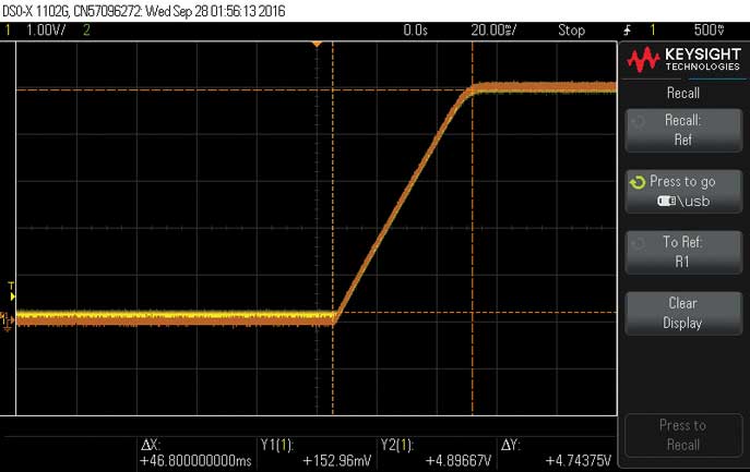
Figure 4. The LT8640. C8 = 0.1 μF, with a startup time of ~50 ms for 0 A (yellow) and 4 A (brown) load currents.
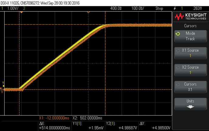
Figure 5. The LT8640. C8 = 1 μF, startup time is ~500 ms, and load current does not affect startup time.
The LT8362 does not include the soft start equation in its data sheet. Using the demo board (Figure 6), a test for soft start timing can be done by changing the values of the soft start capacitor C6 and testing for three different load current values: 0 A (no load), 0.19 A, and 0.38 A.

Figure 6. The LT8362 demo board schematic. C6, the soft start capacitor and load current will be changed.
In Figure 7, C6 = 0.22 μF, the load current is 0.19 A (yellow) and 0.38 A (brown). When the load is increased the soft start timing increases. There is ~10 ms startup time difference, 45 ms that changed to ~55 ms. Notice the waviness exhibited by the initial behavior. This effect is a result of testing with a digital load that strives to maintain a constant resistance value while the output undergoes rapid changes. The digital load is set to CR (constant resistance). If the load is changed to a purely resistive load, a more stable and monotonic startup behavior is observed, as shown in Figure 8. Since the timing results are almost the same between the digital load and the resistive load, the testing for startup differences can continue using the digital load.
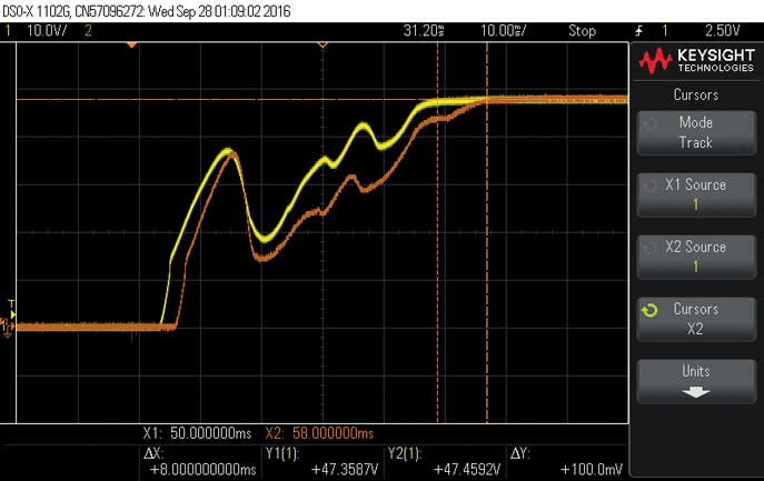
Figure 7. C6 = 0.22 μF. Changing the load current from 0.19 A to 0.38 A changes the soft start time.
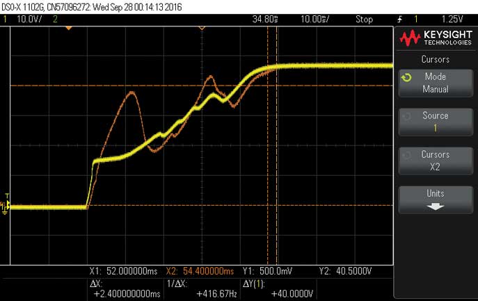
Figure 8. CSS = 0.22 μF, digital load at CR (brown) vs. resistive load (yellow), 0.19 A.
In Figure 9, C6 was changed to 2.2 μF and the startup time changed in comparison to Figure 8 from ~45 ms to ~500 ms for 0.19 A (yellow) and from ~55 ms to ~580 ms for 0.38 A (orange), which is close to 10 times the value like the soft start capacitor ratio. But now, in contrast to the LT8640, which uses a voltage soft start, the load current influences the soft start timing. The result shows that a wavy effect that was shown in Figure 7 is reduced, but there is some ripple on the startup waveform. Figure 10 shows a comparison between the digital load waveform (brown) and the result from a pure resistive load (yellow), which shows that a sudden change makes the digital load jump to an incorrect value but then compensates and its average value. The startup timing and average value of the digital load eventually align with those of the pure resistive load. These observations indicate that while the load current does influence the soft start timing in this scenario, the digital load is still able to compensate and achieve similar results to a pure resistive load.
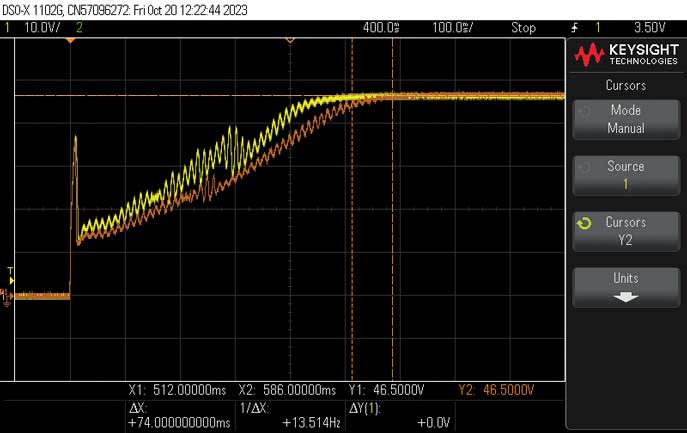
Figure 9. C6 = 2.2 μF startup time change when changing the load current from 0.19 A to 0.38 A.

Figure 10. C = 2.2 μF, longer startup time makes it easier for the digital load to set the correct CR.
Sometimes for powering RF amplifiers there is a preference to bring up the power supply first and then to connect the load. This approach ensures that the power supply is brought up when there is very low or no load current, which helps reduce the inrush current. This scenario is presented in Figure 11, and the result is the startup time shortens to ~12 ms. Even when using a digital load in CC (constant current) mode, where the load is set to a specific value like 0.19 A or 0.38 A, it is still possible to observe a startup time of ~12 ms—similar to no load connected. CC can mean a high impedance to the DC-to-DC converter, so care must be taken to accurately measure the soft start timing correctly in all possible scenarios.
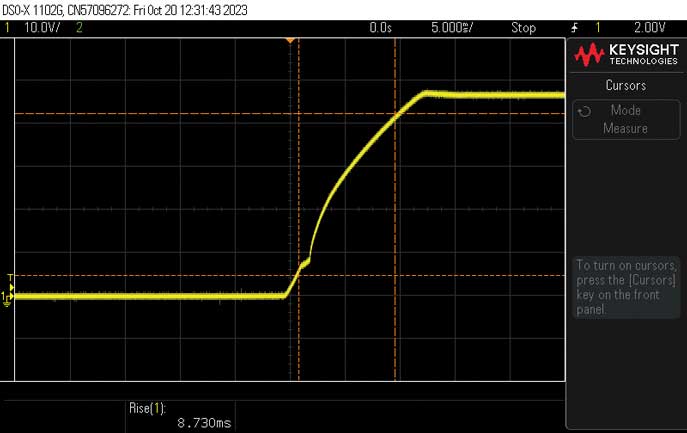
Figure 11. C6 is 0.22 μF, no load current.
When the soft start equation is not included, LTspice® can be a useful tool for predicting the behavior of the circuit. Figure 12 is the LTspice simulation result of the measurement taken in Figure 10 that shows a startup time of ~500 ms. The simulation of no load and 0.19 A currents, when a soft start capacitor of 0.22 μF was used, also shows the correct results of ~12 ms and ~50 ms, as shown in figures 11 and 8. By utilizing LTspice simulations, it becomes possible to predict the behavior of the circuit and estimate the soft start timing even when the soft start equation is not explicitly provided. This can be a valuable tool for understanding and optimizing the performance of the circuit.
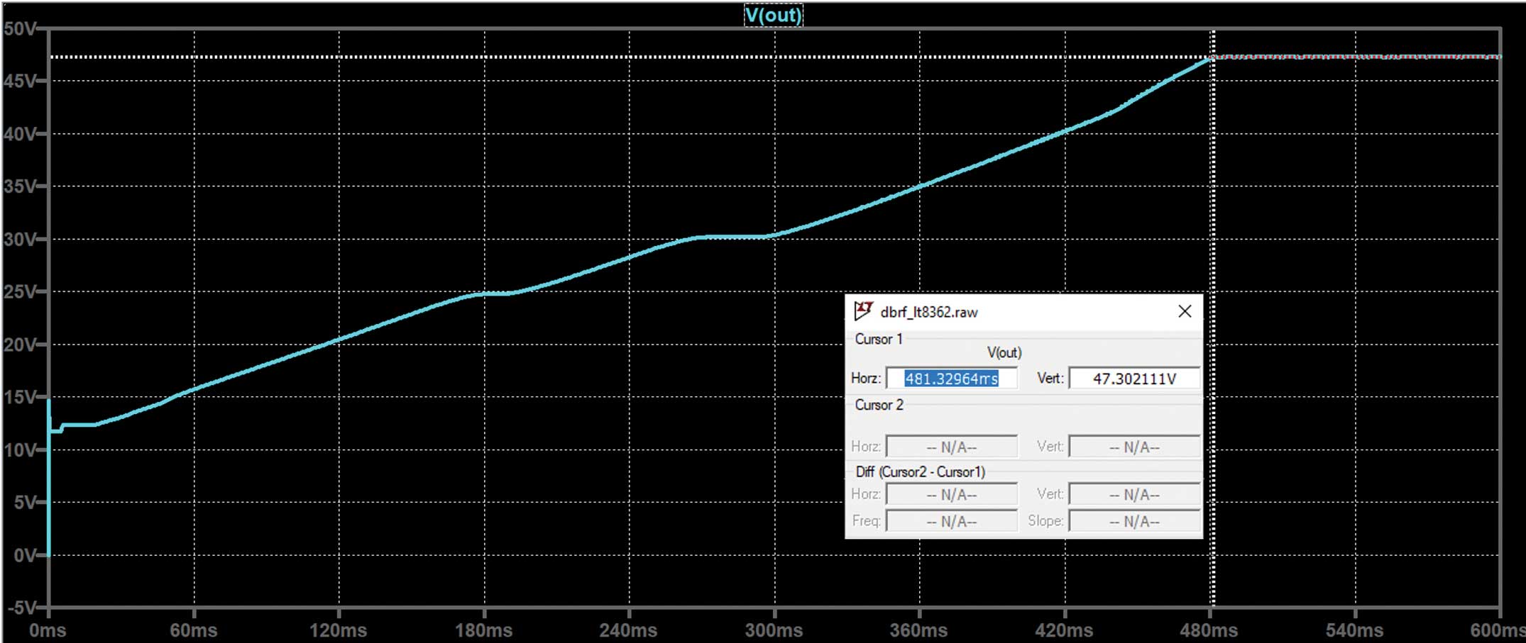
Figure 12. The LTspice simulation of the LT8362 startup waveform, which corresponds to Figure 10.
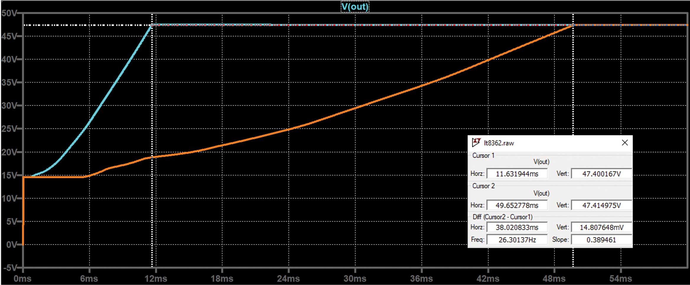
Figure 13. The LTspice simulation of the LT8362 shows correct results, and corresponds to Figure 11 and Figure 8.
Adding Soft Start When There Isn’t One:
When there is no soft start in an IC, the current that the IC will attempt to supply to the output capacitors, if they are not charged, is its maximum current, or current limit value. To add soft start capability, additional discrete components are required, such as an RC combination to provide a time delay, and optionally, a diode or a FET for protection. The LT3990 is a buck regulator that has 62 V/ 0.35 A FETs, very low IQ (quiescent current), AEC-Q100 qualification, a wide frequency operation range, and very low output voltage ripple. However, it does not include a soft start function. The data sheet specifies a typical switch current limit of 0.7 A. To evaluate the behavior of the LT3990 before and after adding discrete components for a soft start function, the built-in example LTspice circuit (shown in Figure 14) can be used. The circuit converts 10 V to 5 V/0.35 A. By simulating the circuit, it is observed that without a soft start function, the inductor current reaches the typical current limit value at startup (Figure 15).

Figure 14. The LTspice built-in demo circuit for the LT3990.
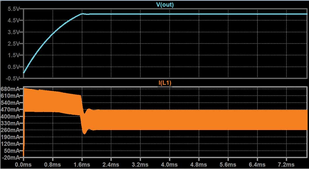
Figure 15. The LT3990 inductor current reaching current limit at startup.
Adding a simple RC combination and a protection diode across the FB pin can provide a gradual increase in FB voltage, which slows down the startup voltage and reduces the inrush current (Figure 16). Figure 17 illustrates the simulation of the circuit demonstrating an initial current surge, albeit of shorter duration. This approach allows for a controlled ramp-up of both the current and output voltage, providing a cost-effective means of incorporating a soft start function. However, it is important to consider that this solution may have an impact on the power good (PG) pin. The PG pin will exhibit a slower ramp-up due to the soft start circuit, which may make this solution unsuitable for certain designs that rely on a fast power-good signal.

Figure 16. Adding C4, R6, and D1 to bias the LT3990 FB pin and slow down the startup behavior.
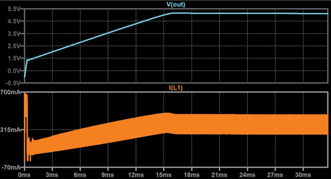
Figure 17. The simulation result still shows peak current, but slower ramp behavior.
To completely eliminate the surge current during startup, an alternative approach is to add a series resistor that will be bypassed by a FET. The time duration that it will take for the FET to reach its Vgs(th) rating and start conducting is determined by an RC constant and the input power supply. Figure 18 illustrates an example circuit that incorporates this approach, and Figure 19 shows the simulation result. By using this configuration, the surge current is effectively eliminated during startup. The RC constant, determined by the resistor and capacitor values, along with the input power supply characteristics, determines the time it takes for the FET to reach its threshold voltage and start conducting. This allows for a controlled and gradual increase in the output voltage and current, eliminating the surge current typically associated with startup.

Figure 18. Adding M1 and RC will bypass the R5 limiting resistor.
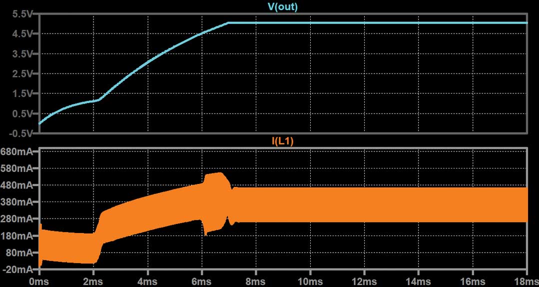
Figure 19. The current is first limited by R5, no current surge, when Vgs(th) is reached current ramps up gradually.
This method provides a reliable way to implement a soft start function and ensure a smooth and controlled startup without any surge current. However, it is important to carefully select the resistor, capacitor, and FET values to achieve the desired soft start behavior while considering the power supply and load requirements of the circuit.
The PG pin for this simulation may also not behave normally as expected from an open drain so it may not fit all designs.
Conclusion
There are voltage soft start and current soft start implementations. The relationship between soft start time tSS to CSS is typically linear for voltage mode soft start. However, for current mode soft start the equation becomes more complicated due to the dependence on load current, output voltage, and output capacitance. The data sheet may not provide an explicit equation for current mode soft start, and it may be necessary to test different load current scenarios to understand the minimum and maximum values of the soft start timing. A good way to predict tSS for parts that use current soft start, is to simulate for it using LTspice. For ICs that do not include a built-in soft start function, additional components are required to generate a gradual increase in the output voltage. Without these components, the IC will provide its maximum current capability upon turn-on, which may not be desirable in certain applications. In summary, when implementing soft start, it is important to understand the specific implementation (voltage mode or current mode), and test different load scenarios to determine the soft start timing.