Abstract
When optimizing data acquisition (DAQ) systems, designers must carefully consider the effects of power supplies on high precision performance. Often, the power supply circuitry includes a combination of low dropout linear regulators and dc-to-dc switch-mode converters. One drawback of switch-mode converters is that they produce an output ripple. While the ripple magnitudes are relatively low, they can couple into key components in the analog signal path that could corrupt measurements and compromise performance. Power components must typically be low noise with adequate supply decoupling at multiple locations on the PCB to prevent performance degradation of the signal chain.
Power supply rejection ratio (PSRR) is a metric that quantifies a system’s ability to reject supply noise and perturbations. As DAQ solutions evolve to be more complete signal chain solutions via system-in-package (SiP) technology, the supply decoupling can be co-packaged with the precision signal chain to improve the overall system PSRR.
PSRR Definition
Power supply rejection ratio, also referred to as power supply ripple rejection, is essentially the ratio of change in supply voltage to the output voltage expressed in dB.
The following equation defines how to calculate PSRR (A2V is the voltage gain).

PSRR is a key parameter that quantifies a circuit’s sensitivity to supply noise and perturbations and how it affects the circuit’s output. It’s typically measured over a wide frequency range from dc up to several MHz, with PSRR tending to degrade at higher frequencies.
System designers often add decoupling capacitors to the power supply nodes of their circuit to reduce noise and glitches that could couple into sensitive components. For amplifiers, 0.1 µF ceramic capacitors are placed as close to the power supply pins as possible to reduce high frequency coupling. In addition, to provide low frequency decoupling, large 10 μF tantalum capacitors are connected in parallel, and typically placed closer to the supply source.
PSRR Motivation
The desire for power efficiency is one reason why some system designers can’t tolerate high power, low noise power conversion components. Battery-powered DAQ systems are an example of an application that requires high performance at low power—a significant motivator for designing DAQs with less sensitivity to power supply noise.
Modern devices often include several systems powered from the same battery. If the current consumption for one system or device increases under certain conditions, the battery voltage, and therefore any supply voltage to other devices powered from said battery, can vary. For these reasons, dc PSRR is important when designing the battery management circuitry of a system. Depending on how sensitive the system is, a designer can use LDO regulators to help combat voltage drops. AC PSRR is also an important specification in battery-powered systems if a ripple-inducing buck, boost, or inverting regulator is required.
For industrial applications, system noise is a key specification. For example, electromagnetic interference (EMI) from nearby sources can couple to the supplies, causing noise spurs and other errors. To help minimize these noise spurs, it is important to use decoupling capacitors and proper PCB design techniques such as grounding, shielding, and proper component placement.
Figure 1 shows a typical precision data acquisition system signal chain. Each component is affected by power supply noise to a different degree. Adding proper decoupling capacitance improves PSRR performance at higher frequencies for each of the components in the signal chain shown in Figure 1.

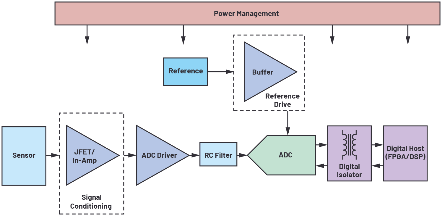
Analog Devices signal chain µModule® data acquisition solutions help solve some of the power design pain points, such as optimized layout of traces, the addition of decoupling capacitors, and in some cases, power management components such as LDO regulators. The ADAQ4003 is a µModule data acquisition solution that includes decoupling capacitors on all supplies to reduce their sensitivity to perturbations. The ADAQ7980/ADAQ7988 µModule data acquisition systems include decoupling capacitors and an LDO regulator. The integrated LDO regulator further simplifies design—system designers only need to provide one clean supply to power the µModule device and they are free to bypass the LDO regulator if required.
Current Method for Testing PSRR on Discrete Components
PSRR testing of discrete components is a common feature in a characterization plan, as it utilizes a methodology of well-established standards and methods. The PSRR test of a discrete component is usually performed without any external supply decoupling capacitance, intentionally revealing the direct impact on performance of substantial noise on the power supply rails.
Usually, a function generator and scope, or network analyzer, can be used to characterize the PSRR of an amplifier by injecting various frequency tones into the dc supply voltage and measuring the amount of perturbation at the DUT’s output.

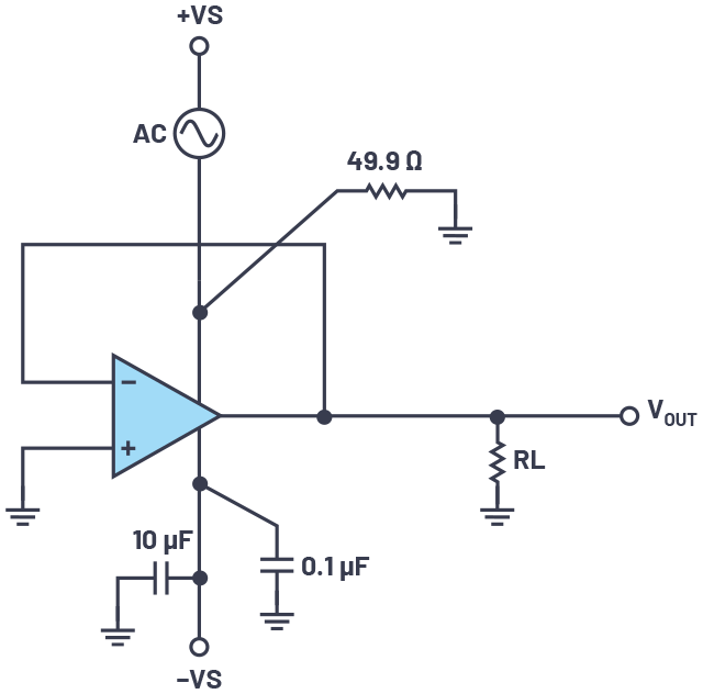
Performing an ac PSRR test on a discrete part requires injecting the ac signal into the dc supply voltage and measuring the output disturbance relative to stimulus on the supply. For example, the ADA4945 has a PSRR of 115 dB at a frequency 100 kHz. This means that a 1 VPEAK, 100 kHz ac disturbance on the supply manifests as an approximately 1.79 µVPEAK signal at the output of the device.

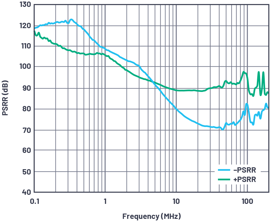
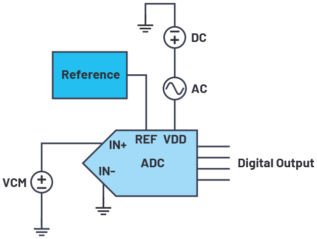
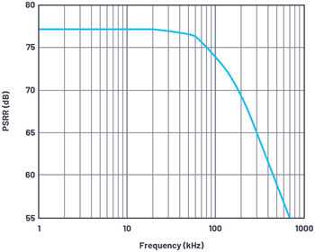
Testing PSRR performance of an ADC is similar to testing an amplifier, but instead of voltage out, it codes out. For ac PSRR, the PSRR of an ADC is the ratio of the power in the ADC output at the frequency to the power of a 200 mV p-p sine wave applied to the ADC VDD supply of frequency. Figure 4 and Figure 5 show the test configuration and resulting typical response for a SAR ADC, respectively.

For dc PSRR testing, the error is the maximum change in the full-scale transition point due to a change in power supply voltage from the nominal value.


The challenge with testing SiPs for PSRR is that they contain multiple internal bypass capacitors up to 30 µF, and most signal generators and network analyzers struggle to drive such large capacitive loads at higher frequencies.
How to Characterize the PSRR of a Signal Chain µModule Solution
When characterizing the PSRR of a signal chain µModule solution, the test methodology is essentially the same as testing an amplifier. An ac signal is superimposed on the dc supply voltage and the relationship between the stimulus on the supply and µModule output is measured. However, due to the internal supply decoupling capacitors, as the input frequencies into the supply increase, so does the need for increased current drive capability from the signal source. The internal capacitance does provide increased immunity to ac PSRR, but the test is intended to account for a worst-case scenario.
Signal chain µModule solutions can be applied in a wide variety of applications, so the PSRR of the SiPs must be tested similarly to a discrete part in the final application. Although there are multiple discrete components, it can be difficult to predict how the full system will respond to the ac supply stimuli.
From a characterization perspective, internal bypass capacitance and proper evaluation board design are the most important things to consider for properly testing PSRR (the evaluation board design is described further in this article in the “Design Considerations for Evaluation Board Development” section). Any internal bypass capacitors improve the ac PSRR of the signal chain µModule solution, but this capacitance affects how the test should be performed.
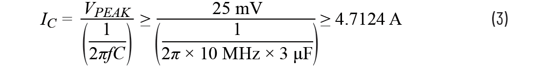
As previously noted, signal generators do not have the capability to drive larger capacitive loads. For example, consider a signal chain µModule solution with a total 3 µF internal bypass capacitance on its main supply, and a PSRR test calling for a maximum frequency of 10 MHz and an amplitude of 50 mV p-p. Based on these conditions, a signal generator producing a sine wave would need to be able to drive approximately 4.71 A of current and have enough bandwidth to handle a 10 MHz signal. This is based on the impedance of the decoupling capacitor at 10 MHz.
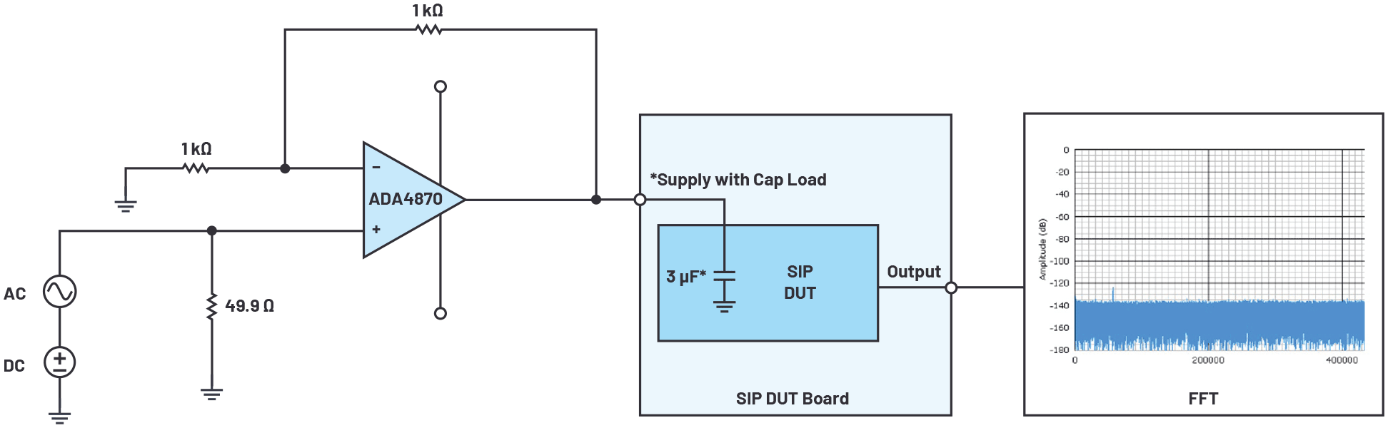
To supply enough current, a high power amplifier such as the ADA4870 can be used to provide additional current sourcing capability. This setup assumes that the function generator being used can provide the necessary dc voltage to bias your DUT. If that’s not the case, a bias tee can be used to isolate the dc and ac signal paths, or you can gain up the available dc bias from a given signal generator that otherwise meets the other necessary output requirements.

Using the ADA4870 evaluation board provides a relatively easy way to interface with an evaluation board and a signal generator since it has SMA inputs and SMA outputs.
Design Considerations for Evaluation Board Development
Designing an evaluation board that can also be used for ac PSRR testing is not grounds for drastically changing the design. Some key points to keep in mind are:
- For each supply that is going to be tested for PSRR, provide an option to drive it via an SMA to maintain signal integrity from the signal source.
- Pay careful attention to reduce any parasitic inductances and capacitances in the path from the SMA input to the associated power plane on the DUT. Any parasitic capacitances or inductances can cause unwanted resonances over the frequencies of interest.
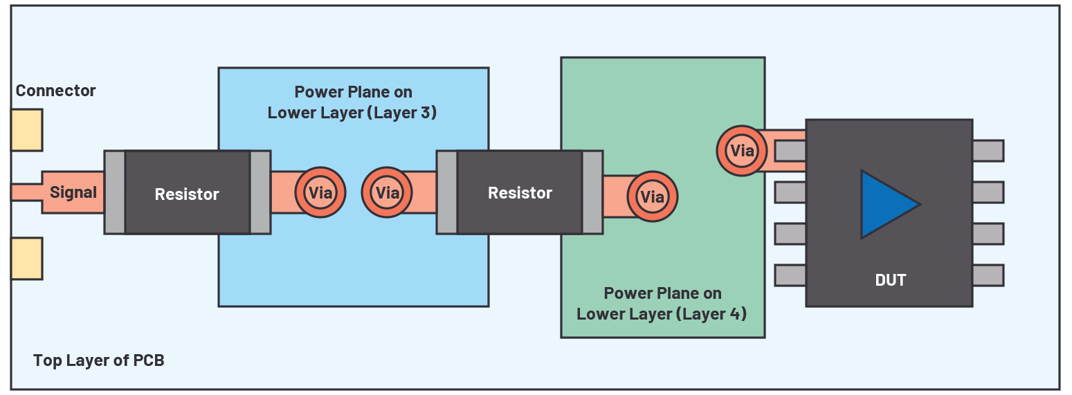
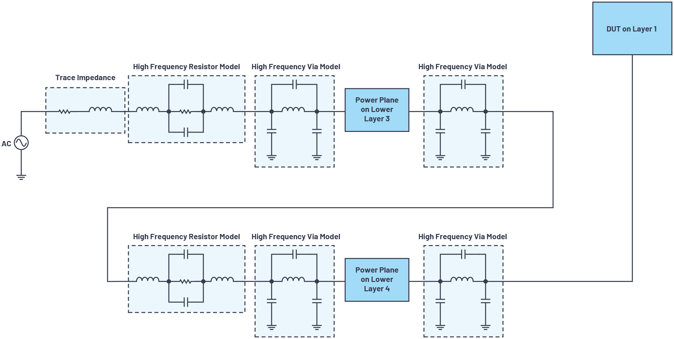
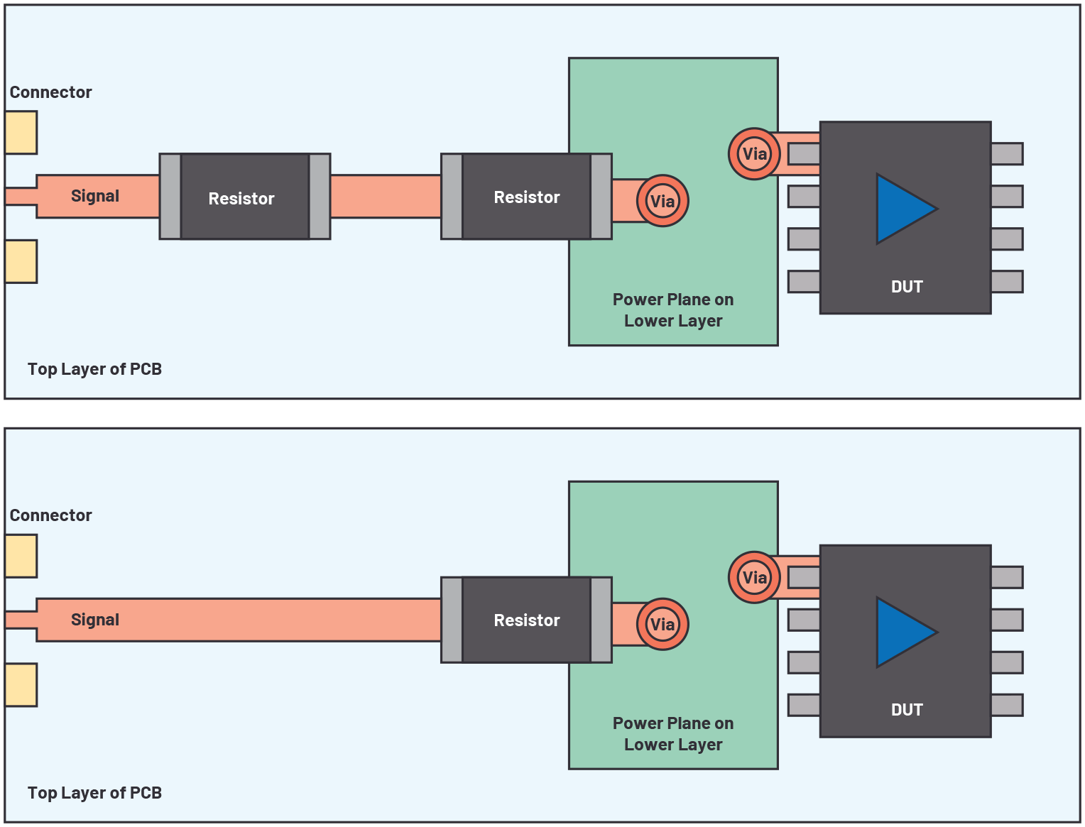
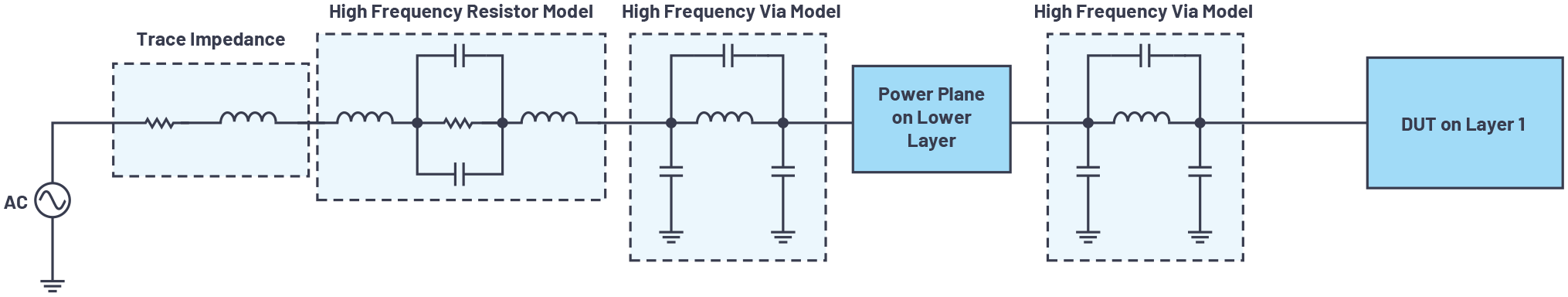
- For each supply, make sure that its associated power plane is solid—that is, not split into multiple sections through passive components and multiple layers. For instance, a current sense resistor should not straddle two power planes (as shown in Figure 7). Also, minimize the number of times the power supply crosses layers to avoid parasitic inductances due to vias, as represented in the high frequency model shown in Figure 8. The resistors shown in Figure 7 could be used for current sensing but, in this case, they are 0 Ω. Figure 9 shows better PCB power plane routing, while Figure 10 shows the high frequency equivalent model.


It’s important that the evaluation board be tested without a DUT to make sure there aren’t any unwanted resonances in the frequency range of interest. If there are any resonances, then it should be accounted for during data processing. For each frequency, scope verify that the supply signal matches expectations—don’t trust the dials on the signal generator.
Test Setup
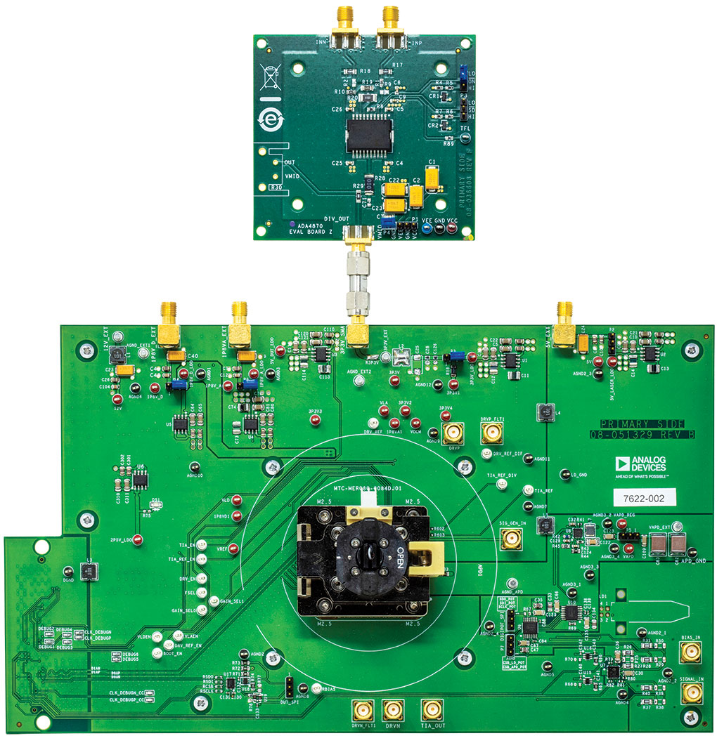
As previously noted, the supply for the signal chain µModule solution under test must be able to provide the nominal dc offset to power the DUT plus an ac stimulus at sufficient current at the maximum input frequency. To accomplish this in the test setup shown here, the ADA4870 evaluation board is used in a noninverting gain of two in combination with an AD3256 function generator.
Figure 11 shows a customized ADA4870 power amplifier evaluation board and the ADA4355 evaluation board.

The data shown in Figure 12 was generated by capturing data at each input frequency and looking at the power of the FFT (dBFS) at each of those frequencies. From there, the voltage level at that frequency was solved by using Equation 4:

Use the resulting VOUT_PSRR to calculate the PSRR:


Conclusion
Analog Devices signal chain µModule solutions integrate signal conditioning, supply generation, and passive internal components. These all-in-one, system in a package designs enable customers to quickly achieve desired, ready for market performance in a very small PCB footprint. Although signal chain µModule solutions are unmatched in ease of use, appropriate testing must be done. While the standard practices of testing PSRR can be applied, additional current drive capability is often necessary due to standard equipment limitations.
References
“Op Amp Power Supply Rejection Ratio (PSRR) and Supply Voltages.” Analog Devices, Inc., 2009.
Reeder, Rob. “Designing Power Supplies for High Speed ADC.” Analog Devices, Inc., February 2012.
Morita, Glenn. “Understand Low Dropout (LDO) Regulator Concepts to Achieve Optimal Designs.” Analog Dialogue, Vol. 48, No. 12, December 2014.
Walsh, Alan. “Powering a Precision SAR ADC Using a High Efficiency, Ultralow Power Switcher in Power Sensitive Applications.” Analog Devices, Inc., March 2016.

