Designing Power Supplies for High Speed ADC
Designing clean power supplies for high speed ADCs can be challenging with so many power options that are available to the designer today. This is especially important when utilizing efficient switching power supplies rather than traditional LDOs. In addition, most ADCs do not adequately specify high frequency power supply rejection, a key factor when selecting the proper supply.
This technical article describes techniques to measure a converter’s AC power supply rejection, thereby establishing a baseline for the converter’s power supply noise sensitivity. A simple noise analysis of an actual power supply is given to show the user how to apply these numbers in a design to verify the power supply is adequate for the converter(s) chosen. In summary, some simple guidelines are described in order to give the user some guidance in designing power supplies for high speed converters.
Many of today’s applications require high speed sampling analog-to-digital converters (ADC) with resolutions of 12 bits or more, as the higher resolution allows users to develop more accurate system measurements. Unfortunately, higher resolution also implies that the system will be more sensitive to noise. Every time the system resolution increases by one bit, for example, 12 bits to 13 bits, the system sensitivity goes up by a factor of two. Thus, when designing with ADCs, it is crucial that designers consider the noise contributions from an often forgotten source—the system power supply. ADC are sensitive devices and each input, that is, analog, clock, and power should be treated equally to achieve the best performance as specified in the data sheet. Noise sources are abundant and can come in many forms and be emitted or radiated affecting the performance.

Figure 1.
All the buzz and hype in today’s electronic world is that new cost-down designs are “going green”. Keeping power low requires less thermal management, keeping power efficiency maximized and batteries happy when it comes to portable applications. However, most ADC data sheets suggest that linear power supplies be used because their noise is lower than that of switching type supplies and in some cases that may be entirely true. However, new advances in technology have proven that switching power supplies could possibly be used in communications and medical applications (see the “How to Test Power Supply Rejection Ratio (PSRR) in an ADC” article in the References section).
This article describes different test measurement methods that are critical to understanding power supply design for a high speed ADC. Commonly called power supply rejection ratio (PSRR) and power supply modulation ratio (PSMR), both of these tests are useful in determining just how sensitive the converter is too noisy effects on the power supply rails as well as to determine just how quiet the power supply rail must be in order to achieve the expected performance of the ADC itself.
Looking Closer at Analog Power Pins
Typically, a power pin is not thought of as an input. But it is. It can be just as sensitive to noise and distortion as clock and analog input pins are known. Even though the signal that comes onto the power pin is dc in nature and typically doesn’t fluctuate in a repetitive manor it still has some finite amount of noise and distortion riding on the dc bias. This noise can be generated intrinsically or extrinsically which will affect the converter’s performance.
Think of the classic example when there is a noise or jitter present on the converter’s sampling clock signal. Jitter on the sample clock can present itself as both close-in noise and/or it can be in the form of broadband noise as well. Both will depend on the oscillator and system clock circuitry used. Even with an ideal analog input signal presented to an ideal ADC the clock impurities will be resolved on the output spectrum as shown in Figure 2.

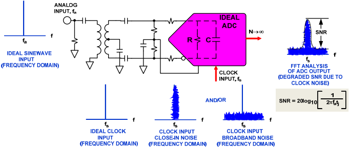
Figure 2. Effect of Sampling Clock Noise on Ideal Digitized Sine Wave
The corollary to this figure is the power pin. Substitute the sampling clock input pin in Figure 2 with an analog power pin (AVDD). The same mechanism applies here too, that any noise, either close-in or broadband, will show itself on the output spectrum in this convolved manor. However, there is a difference; a power pin can be thought of as a broadband input pin with a 40 dB to 60 dB attenuator (depending on the process and circuit topology). In general MOS circuit construction, any source or drain pin is isolated (resistive) in nature from the signal path, thus providing a significant amount of attenuation vs. the gate pin, or signal path. There is some assumption that the design employs the right type of circuit construction to maximize isolation. Some types, such as common-source, may not be well suited when supply noise is evident because the supply is biased through a resistive element, which then connects to the output stage, see Figure 3 and Figure 4. Any modulation, noise, etc on the AVDD pin could show through more easily and affect the local and/or adjacent circuitry. This is why there is always grounds for understanding and seeking PSRR data on converters.


Figure 3. Different Circuit Topologies—Implementation A

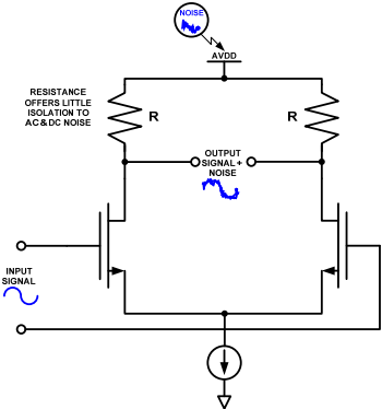
Figure 4. Different Circuit Topologies—Implementation B
As the different implementations suggest there are different frequency characteristics due to parasitic R, C, and mismatch. Remember processes are getting smaller too, with smaller process geometries the more bandwidth and speed available. Taking this into account, this means lower supplies and smaller thresholds. So why not treat a power supply node as a high bandwidth input, similar to a sampling clock or analog input pin.
Power Supply Rejection Defined
There are some terms that govern how well a ADC performs when there is noise on the power supply rail. They are PSRR-dc, PSRR-ac, and PSMR. PSRR-dc is the ratio of the change in power supply voltage to the resulting change in the ADC’s gain or offset error. This can be expressed in fractions of a least significant bit (LSB), a percentage, or logarithmically, in dB (PSR = 20 × log10 (PSRR)), and is usually specified at dc.
However, this method only reveals how one specified parameter of the ADC may change with a change in power supply voltage, and therefore cannot prove the robustness of the converter. A better method is to test supply rejection by riding an ac signal on top of the dc power supply, PSRR-ac, thus actively coupling the signal (noise source) through the converter’s circuitry. This method essentially exercises the attenuation of the converter, reviling itself as a spur (noise) that rises above the noise floor of the converter at some given amplitude. This presents itself as where the converter breaks given a certain amount of injected noise and amplitude. This also gives the designer insight as to how much power supply noise will affect the signal or add to it. PSMR, affects the converter in a different way, it tells the designer just how sensitive the converter is to power noise effects as it modulates with analog input signal applied. The effect is shown as modulation around the IF frequency applied to the converter and can wreak havoc in or around the carrier sidebands if the supply is not carefully designed.
In summary, power supply noise should be tested and treated just like any other input to the converter. It is imperative that the user understands the system supply’s noise. If not, power supply noise will increase the converter noise floor and limit the dynamic range of the entire system.
Power Supply Tests
Figure 6 shows a PSRR measurement of an ADC on a system board. Each supply is measured individually to better gain perspective on the ADC’s dynamic behavior when an ac signal rides on the power supply under test. Start with a high capacitor value such as a 100 µF nonpolarized electrolytic. For the inductor, use a 1 mH to act as the ac blocker to the dc power supply. This is commonly called a bias-T and can be purchased in a packaged-connectorized housing.
Using the oscilloscope measure the amplitude of the ac signal with a scope probe applied to the point at which the power enters the ADC’s supply pin under measurement. To make things simple define the amount of ac signal riding on the supply as a value related to the converter’s input full-scale. For example, if the ADC’s full-scale is 2 V p-p, then use 200 mV p-p or −20 dB. Next, with the input of the converter grounded (no analog signal applied), look for an error spur at the test frequency coming out of the noise floor/FFT spectrum, as shown in Figure 5. To calculate PSRR, simply subtract −20 dB from the error spur value seen on the FFT spectrum. For example, if the error spur shows up at −80 dB from the noise floor, then the PSRR is −80 dB − −20 dB or −60 dB, (PSRR = error spur (dB) − oscilloscope measurement (dB)). The value of −60 dB may not seem like much, but let’s look at that in terms of a voltage, it equates to 1 mV/V (or 10−60/20), which is not uncommon for a PSRR specification in any converter data sheet.


Figure 5. Example of PSRR—FFT Spectrum

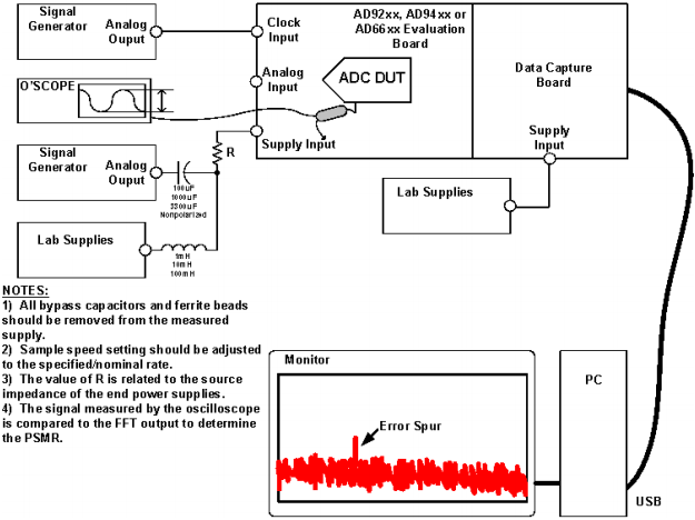
Figure 6. Typical PSRR Testing Setup
The next step is to vary the frequency and amplitude of the ac signal in order to characterize the ADC’s PSRR in your system board. Most data sheet numbers are typical, and might only specify worst-case operating conditions or worst performing supply. For example, the 5 V analog power supply might be the worst relative to the other supplies. Make sure all the supplies are specified or ask the factory for this data if not specified completely. This will allow the designer to place the proper design constraints to each supply.
Keep in mind there is a disadvantage of testing PSRR/PSMR when using an LC arrangement. When sweeping the frequency band of interest, the signal level required at the output of the waveform generator to achieve the desired input level at the ADC supply pin may need to be very high. This is because the LC arrangement will form a notch filter at some frequency depending on the values chosen. This greatly increases ground currents at the notch, which can get into the analog inputs. To get around this, simply swap in new LC values when testing at the frequencies that are causing measurement difficulty. It should also be noted here that losses across the LC network are caused at dc as well. Remember to measure the dc supply at the supply pin of the ADC to compensate for that loss. For example, the 5 V supply may only read 4.8 V on your system board after the LC network. Simply move the power supply voltage up to compensate for the loss.
PSMR is measured essentially the same way as PSRR. However, when measuring PSMR an analog input frequency is applied to the test setup, this is shown in Figure 7.


Figure 7. Typical PSMR Testing Setup
The other difference is the modulation or error signal applied only at low frequency in order to see the mixing effects of this signal with the analog input frequency applied to the converter. It is typical to use 1 kHz to 100 kHz frequencies for this test. The amplitude of this error signal can be relatively constant as long as the error signal, and the mixing products, can be seen around the fundamental. However, it may be worthwhile to change the amplitude of the modulated error signal applied in order to check to make sure this value is constant. To acquire the final result, the difference between the amplitude of the highest (worst) modulation spur relative to the fundamental will determine the PSMR specification. An example of a measured PSMR FFT spectrum is shown in Figure 8.

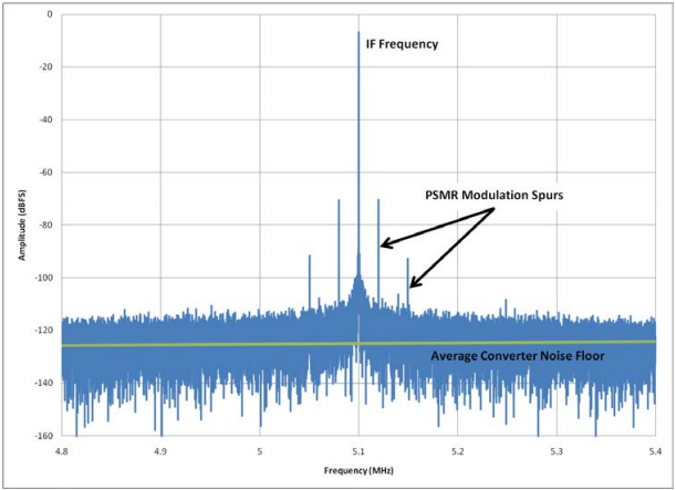
Figure 8. Example of PSMR—Partial FFT Spectrum
Power Supply Noise Analysis
What is important to the converter, and ultimately the system, is that noise on any given input does not affect the performance. Now that PSRR and PSMR have been defined and the significances understood, an example will be described in order to understand how to apply the measured numbers.
The following example shows what to look for and how to design the proper way when it comes to understanding the power supply’s noise meeting the system design needs.
Begin by choosing a converter and then choose a regulator, LDO, switcher, etc. Not just any regulator will do. From the data sheet, check the regulator’s noise and ripple specifications, as well as its switching frequency, if using a switcher. A typical regulator might have 10 µV rms noise over a 100 kHz bandwidth. Assuming the noise is white, this is equivalent to a noise density of 31.6 nV rms/√Hz over the band of interest.
Next, check the converter’s power supply rejection specification to get an understanding of where the converter’s performance will degrade due to noise on the supply. 60 dB (1 mV/V) is typical for most high speed converters over the first Nyquist zone, fS/2. If it is not given, either measure it as described previously or ask the factory contact.
Using a 16-bit ADC with 2 V p-p full-scale input range, 78 dB SNR, and 125 MSPS sampling rate, the noise floor is 11.26 nV rms. The noise from any source must be kept below this to prevent it from being seen by the converter. In the first Nyquist zone, the converter noise will be 89.02 µV rms (11.26 nV rms/√Hz) × √(125 MHz/2). Although the regulator’s noise (31.6 nV/√Hz) is more than twice that of the converter, remember to account for the converter’s 60 dB PSRR, which will suppress the switcher’s noise to 31.6 pV/√Hz (31.6 nV/√Hz × 1 mV/V). This noise is much smaller than the converter’s noise floor, so the regulator’s noise will not degrade the converter’s performance.
Supply filtering, grounding, and layout are important too. Adding 0.1 µF capacitors to the ADC power supply pins will reduce the noise even lower than that calculated previously. Keep in mind that some supply pins draw more current or are more sensitive than others. So use decoupling sparingly but be mindful that an extra decoupling capacitor may be needed on some supply pins. Adding a simple LC filter on the power supply output may also help the reduction of noise as well. However, when using a switcher, a cascaded filter will suppress the noise even more. Remember that a approximately 20 dB/decade is gained for each additional stage.
One final point that should be made about the analysis is that this is for a single converter only. If there are multiple converters or channels involved in a system, things change. For instance, ultrasound employs many ADC channels that are summing digitally to increased dynamic range. What this essentially does is push the noise floor of the converter/ system down by 3 dB each time the channel count is doubled. For instance, using the previous example, the noise floor of the converter will be half (−3 dB) if two converters are used and −6 dB if four converters are used. This is true because each converter can be treated as an uncorrelated noise source. Uncorrelated noise sources can be RSS’ed or root sum squared because these noise sources are independent and have no relationship between each other instantaneously. In the end, this quickly puts a heavier design constraint on the power supply as the number of channels is increased and the noise floor of the system is reduced and becomes more sensitive.
Conclusion
There is no possible way to ensure that all supply noise is eliminated in your application. No system will be totally immune to unwanted power supply interaction. Therefore, as a user of ADCs, the designer must be proactive during the power supply design and layout stage. Here are some useful tips in maximizing PC board noise immunity to supply changes:
- Decouple all power supply rails and bus voltages that come onto the system board.
- Remember that approximately 20 dB/decade is gained for each additional filtering stage.
- Decouple again if supply leads are long and are feeding a particular IC, part, and/or area.
- Decouple for both high and low frequencies.
- Series ferrite beads are commonly used at the power entry point just before the decoupling capacitor to ground. This should be done for each individual supply voltage coming in on the system board whether it be from an LDO or switcher regulator.
- For added capacitance, use tightly stacked power and ground planes (≤4 mil spacing) this adds inherent high-frequency decoupling to the PCB design.
- Like any good board layout, keep supplies away from sensitive analog circuitry such as the front-end stage of the ADC and clocking circuits.
- Good circuit partitioning is key and some components maybe located on the opposite side of the PCB for added isolation.
- Pay attention to ground return paths, particularly on the digital side, so that digital transients don’t find their way back to the analog section of the board. Split ground planes may also be useful in some cases.
- Keep analog and digital referenced components over their respective plane. This common practice ensures added isolation to noise and coupling interactions.
- Follow the IC manufacture recommendations; if they are not directly stated in the application note or data sheet, then study the evaluation board. These are great vehicles to start from.
This technical article is intended to give a clear view of power supply sensitivities as they relate to high speed converters and why it is so important to the user’s system dynamics. One should appreciate the layout techniques and hardware required to achieve data sheet specifications of an ADC on the system board.
About the Authors
Related to this Article
Products
Dual Channel, 12-Bit, 105 MSPS IF Sampling A/D Converter With Analog Input Signal Conditioning
4-Channel DAS with 16-Bit, Bipolar Input, Simultaneous Sampling ADC
16-Bit, 1 MSPS/500 kSPS PulSAR ADCs in MSOP/LFCSP
16-Bit, 1 MSPS/500 kSPS PulSAR ADCs in MSOP/LFCSP
14-Bit, 170 MSPS/250 MSPS, JESD204B, Analog-to-Digital Converter
14-Bit, 170 MSPS/210 MSPS/250 MSPS, 1.8 V Analog-to-Digital Converter (ADC)
8-Channel, 4.8 kHz, Ultralow Noise, 24-Bit Sigma-Delta ADC with PGA
Dual Channel, 12-Bit, 105 MSPS IF Sampling A/D Converter With Analog Input Signal Conditioning
8-Channel, 1MSPS, 12-Bit SAR ADC with Temperature Sensor
Octal, 14-Bit, 40/65 MSPS Serial LVDS 1.8 V A/D Converter
18-Bit, 100 kSPS PulSAR ADCs in MSOP/LFCSP
250 kSPS, 6-Channel, Simultaneous Sampling, Bipolar, 16-Bit ADC
250 kSPS, 6-Channel, Simultaneous Sampling, Bipolar 16-Bit ADC
250 kSPS, 6-Channel, Simultaneous Sampling, Bipolar 16-Bit ADC
Quad, 16-Bit, 125 MSPS Serial LVDS 1.8 V Analog-to-Digital Converter
Integrated Multi-Format SDTV / HDTV Video Decoder and RGB Graphics Digitizer
CMOS Microprocessor-Compatible 12-Bit A/D Converter
128 Channel, 24-Bit Current to Digital ADC
64-Channel, 24-Bit Current-to-Digital ADC
32-Channel, 24-Bit Current-to-Digital ADC
Fast, Complete 12-Bit A/D Converters
12-Bit Successive-Approximation Integrated Circuit ADC
Complete, High Resolution 16-Bit A/D Converters
Integrated Single Supply Broadband Modem Mixed Signal Front End (MxFE®)
10-Bit CCD Signal Processor with Precision Timing™ Core
Complete 12-Bit, 25 MHz CCD Signal Processor
Complete 10-Bit, 25 MHz CCD Signal Processor
CCD Signal Processor with Precision Timing™ Generator
Mixed Signal Front End Set Top Box, Cable Modem (MxFE®)
Low Cost, 3.3 V, CMOS Mixed Signal Front End (MxFE®) for Broadband Applications
Single Supply Cable Modem/Set Top Box Mixed Signal Front End (MxFE®)
Integrated Single Supply Broadband Modem Mixed Signal Front End (MxFE®)
Integrated Single Supply Broadband Modem Mixed Signal Front End (MxFE®)
Low Power IF Digitizing Subsystem
Analog Front End Converter for Set-Top Box, Cable Modem
Analog Front End Converter for Set-Top Box, Cable Modem
IF Digitizing Subsystem
Broadband Modem Mixed-Signal Front End
Broadband Modem Mixed-Signal Front End
Broadband Modem Mixed-Signal Front End
12-Bit Broadband Modem Mixed Signal Front End (MxFE®)
12-Bit Broadband Modem Mixed Signal Front End (MxFE®)
Broadband Modem Mixed-Signal Front End
IF Digitizing Subsystem
Mixed-Signal Front-End (MxFE™) Baseband Transceiver for Broadband Applications
12-/14-Bit Mixed Signal Front-End (MxFE®) Processor for Broadband Communications
Mixed-Signal Front-End (MxFE™) Baseband Transceiver for Broadband Applications
10-/12-Bit Mixed Signal Front-End (MxFE®) Processor for Broadband Communications
Complete 12-Bit 30 MSPS CCD Signal Processor
Correlated Double Sampler (CDS)
12-Bit 40 MSPS Imaging Signal Processor
12-Bit 40 MSPS Imaging Signal Processor
16-Bit, 200 kSPS, Serial I/O A/D Converter
16-Bit, 100 kSPS, Serial I/O A/D Converter
16-Bit, 200 kSPS, Parallel I/O A/D Converter
16-Bit, 100 kSPS, Parallel I/O A/D Converter
4-Channel, 16-Bit, 200 kSPS Data Acquisition System
16-Bit, 25 MSPS/65 MSPS/80 MSPS/105 MSPS, 1.8 V Dual Analog-to-Digital Converter (ADC)
14-Bit, 20/40/65/80 MSPS, 1.8 V Analog-to-Digital Converter
14-Bit, 125 MSPS/105 MSPS, 1.8 V Dual Analog-to-Digital Converter
Dual, 14-Bit, 80 MSPS/125 MSPS Serial LVDS 1.8 V Analog-to-Digital Converter
14-Bit, 80 MSPS/155 MSPS, 1.8V Dual, Serial Output A/D Converter
14-Bit, 170 MSPS/210 MSPS/250 MSPS, 1.8 V Dual Analog-to-Digital Converter (ADC)
14-Bit, 170 MSPS/210 MSPS/250 MSPS, 1.8 V Analog-to-Digital Converter (ADC)
14-Bit, 80 MSPS/155 MSPS, 1.8 V Serial Output Analog-to-Digital Converter (ADC)
14-Bit, 80/105/125/150 MSPS, 1.8 V Dual Analog-to-Digital Converter
Quad 12-Bit, 170/210 MSPS, Serial Output 1.8 V A/D Converter
Octal, 12-Bit, 40/80 MSPS Serial LVDS 1.8 V A/D Converter
Dual, 12-Bit, 80 MSPS/125 MSPS Serial LVDS 1.8 V Analog-to-Digital Converter
12-Bit, 170 MSPS/210 MSPS/250 MSPS, 1.8 V Analog-to-Digital Converter
12-Bit, 170 MSPS/210 MSPS/250 MSPS, 1.8 V Analog-to-Digital Converter
Quad, 12-Bit, 80/105/125 MSPS, Serial LVDS 1.8 V ADC
12-Bit, 20 MSPS/40 MSPS/65 MSPS/80 MSPS, 1.8 V Analog-to-Digital Converter
12-Bit, 125/105 MSPS, 1.8 V Dual Analog-to-Digital Converter
11-Bit, 105 MSPS/150 MSPS, 1.8 V Dual Analog-to-Digital Converter
12-Bit, 80 MSPS/105 MSPS/125 MSPS/150 MSPS, 1.8 V Dual Analog-to-Digital Converter
12-Bit, 170 MSPS/210 MSPS/250 MSPS, 1.8 V Analog-to-Digital Converter
12-bit, 170/210/250 MSPS, 1.8 V Dual Analog-to-Digital Converter (ADC)
10-Bit, 20 MSPS/40 MSPS/65 MSPS/80 MSPS, 1.8 V Analog-to-Digital Converter
10-Bit, 125/105 MSPS, 1.8 V Dual Analog-to-Digital Converter
10-Bit, 200 MSPS/250 MSPS 1.8 V Analog-to-Digital Converter
10-Bit, 105 MSPS/125 MSPS/150 MSPS, 1.8 V Dual Analog-to-Digital Converter
High Speed Monolithic Pulse Width Modulator
8-Bit, 500 MSPS, 1.8 V Analog-to-Digital Converter
Triple 8-Bit Monolithic A/D Converter
8-Bit, 250 MSPS, 3.3 V A/D Converter
8-Bit, 250 MSPS, 3.3 V A/D Converter
16-Bit, 200 MSPS/250 MSPS Analog-to-Digital Converter
16-Bit, 130 MSPS A/D Converter
16-Bit, 80 MSPS/105 MSPS ADC
16-Bit, 80 MSPS / 100 MSPS A/D Converter
14-Bit, 105 MSPS / 125 MSPS A/D Converter
14-Bit, 80 MSPS A/D Converter
12-Bit, 370 MSPS/500 MSPS, 1.8 V Analog-to-Digital Converter
12-Bit 105/125 MSPS Analog-To-Digital IF Sampling Converter
12-Bit, 105 MSPS Analog-to-Digital Converter
12-Bit, 170/210 MSPS 3.3 V A/D Converter
10-Bit, 170/200 MSPS 3.3 V A/D Converter
10-Bit, 210 MSPS ADC
Quad 8-Bit, 65 MSPS, Serial LVDS A/D Converter
Quad, 8-Bit, 100 MSPS Serial LVDS 1.8 V A/D Converter
8-Bit, 500 MSPS, 1.8 V Analog-to-Digital Converter (ADC)
8-Bit, 250 MSPS, 1.8 V Dual Analog-to-Digital Converter (ADC)
8-Bit, 50 MSPS/80 MSPS/100 MSPS ADC
Dual Channel 8-Bit Resolution CMOS ADC
8-Bit, Complete, 32 MSPS A/D Converter
Octal LNA/VGA/AAF/ADC and CW I/Q Demodulator
Octal LNA/VGA/AAF/ADC and CW I/Q Demodulator
Octal LNA/VGA/AAF/14-Bit ADC and CW I/Q Demodulator
Octal LNA/VGA/AAF/12-Bit ADC and CW I/Q Demodulator
Octal LNA/VGA/AAF/ADC and Crosspoint Switch
Octal LNA/VGA/AAF/ADC and Crosspoint Switch
Octal LNA/VGA/AAF/ADC and Crosspoint Switch
16-Bit, 20 MSPS/40 MSPS/65 MSPS/80 MSPS, 1.8 V Dual Analog-to-Digital Converter
16-Bit, 125 MSPS/105 MSPS/80 MSPS, 1.8 V Dual Analog-to-Digital Converter
10 MHz Bandwidth, 640 MSPS Dual Continuous Time Sigma-Delta Modulator
16-Bit, 20/40/65/80 MSPS, 1.8 V Analog-to-Digital Converter
16-Bit, 125 MSPS/105 MSPS/80 MSPS, 1.8 V Analog-to-Digital Converter
16-Bit, 2.5 MHz/5 MHz/10 MHz, 30 MSPS to 160 MSPS Dual Continuous Time Sigma-Delta ADC
16-Bit, 10 MHz Bandwidth, 30 MSPS to 160 MSPS Continuous Time Sigma-Delta ADC
16-Bit High Speed Oversampled A/D Converter
Quad, 14-Bit, 50 MSPS Serial LVDS 1.8 V ADC
14-Bit, 125 MSPS, 1.8 V Dual Analog-to-Digital Converter (ADC)
Octal, 14-Bit, 40/65 MSPS Serial LVDS 1.8 V A/D Converter
14-Bit, 125 MSPS/105 MSPS/80 MSPS, 1.8 V Analog-to-Digital Converter
14-Bit, 150 MSPS, 1.8 V Analog-to-Digital Converter
Quad, 14-Bit, 80 MSPS/105 MSPS/125 MSPS Serial LVDS 1.8 V Analog-to-Digital Converter
Octal, 14-Bit, 50 MSPS, Serial LVDS, 1.8 V ADC
14-Bit, 20 MSPS/40 MSPS/65 MSPS/80 MSPS, 1.8 V Dual Analog-to-Digital Converter
Dual 14-Bit, 20/40/65 MSPS, 3 V Analog-to-Digital Converter
14-Bit, 80 MSPS/105 MSPS/125 MSPS, 1.8 V Analog-to-Digital Converter
14-Bit, 20 MSPS/40 MSPS/65 MSPS/80 MSPS 3 V A/D Converter
14-Bit 40/65 MSPS IF Sampling Analog-To-Digital Converter
Complete 14-Bit, 3 MSPS Monolithic A/D Converter
Complete 14-Bit, 1.25 MSPS Monolithic A/D Converter
Complete 14-Bit, 10 MSPS Monolithic A/D Converter
Quad, 12-Bit, 170 MSPS/210 MSPS/250 MSPS Serial Output 1.8 V ADC
12-Bit, 20 MSPS/40 MSPS/65 MSPS, Dual A/D Converter
12-Bit, 20/40/65 MSPS 3 V Low Power A/D Converter
12-Bit, 80 MSPS, 3 V A/D Converter
12-Bit, 20/40/65 MSPS, 3 V Analog-to-Digital Converter
12-Bit, 20 MSPS/40 MSPS/65 MSPS/80 MSPS, 1.8 V Dual Analog-to-Digital Converter
11-Bit, 200 MSPS, 1.8 V Analog-to-Digital Converter
12-Bit, 170 MSPS/210 MSPS/250 MSPS, 1.8 V Analog-to-Digital Converter
Quad 12-Bit, 50/65 MSPS, Serial LVDS A/D Converter
Quad, 12-Bit, 40/65 MSPS Serial LVDS 1.8 V A/D Converter
12-Bit, 65 MSPS Analog-to-Digital Converter
12-Bit , 25 MSPS Monolithic A/D Converter
12-Bit 40 MSPS Monolithic A/D Converter
12-Bit, 3.0 MSPS A/D Converter
Octal, 12-Bit, 40/50/65 MSPS Serial LVDS 1.8 V A/D Converter
Complete 12-Bit 1.25 MSPS Monolithic A/D Converter
Complete 12-Bit, 10.0 MSPS Monolithic A/D Converter
Quad, 10-Bit, 40/65 MSPS Serial LVDS 1.8 V A/D Converter
10-Bit, 40/65/80/105 MSPS 3 V Dual Analog-to-Digital Converter
10-Bit, 65/80/105 MSPS Dual A/D Converter
10-Bit, 65/80/105 MSPS 3 V A/D Converter
10-Bit, 65 MSPS/80 MSPS/105 MSPS 3 V Analog-to-Digital Converter
Octal, 10-Bit, 40 MSPS/65 MSPS, Serial LVDS, 1.8 V ADC
10-Bit, 200 MSPS/250 MSPS/300 MSPS, 1.8 V Analog-to-Digital Converter
10-Bit, 20 MSPS/40 MSPS/65 MSPS/80 MSPS, 1.8 V Dual Analog-to-Digital Converter
10-Bit, 40 MSPS, Low-Power Analog-to-Digital Converter
Dual Channel 20 MHz 10-Bit Resolution CMOS ADC
10-Bit, 20 MSPS, 80 mW CMOS A/D Converter
10-Bit, 100 MSPS, TTL A/D Converter
10-Bit, 100 MSPS, ECL A/D Converter
Dual, 6-Bit, 60 MSPS Monlithic A/D Converter
Dual 8-Bit, 60 MSPS A/D Converter
Dual 8-Bit 50 MSPS A/D Converter
8-Bit, 40/60/80 MSPS A/D Converter
8-Bit, 200 MSPS/135 MSPS A/D Converter
10-Bit, 60 MSPS A/D Converter
10-Bit, 40 MSPS/60 MSPS A/D Converter
Monolithic 8-Bit Video A/D Converter
12-Bit, 41 MSPS Monolithic A/D Converter
High Speed 8-Bit TTL A/D Converter
High Speed 8-Bit Monolithic A/D Converter
Obsolete
Obsolete
Obsolete
10-Bit 20 MSPS 160 mW CMOS A/D Converter
Complete 12-Bit 10 MSPS Monolithic A/D Converter
Obsolete
Complete 12-Bit 5 MSPS Monolithic A/D Converter
4-Channel, 8-Bit ADC with I2C Compatible Interface in 8-Lead SOT-23
8-Channel, 12-Bit ADC with I2C Compatible Interface in 20-Lead TSSOP
8-Channel, 10-Bit ADC with I2C Compatible Interface in 20-Lead TSSOP
4-Channel, 10-Bit ADC with I2C Compatible Interface in 8-Lead SOT-23
4 Channel, 12-Bit ADC with I2C Compatible Interface in 16-Lead TSSOP
4-Channel, 10-Bit ADC with I2C Compatible Interface in 16-Lead TSSOP
2-Channel, 12-Bit ADC with I2C Compatible Interface in 10-Lead MSOP
4-Channel, 12-Bit ADC with I2C Compatible Interface in 8-Lead SOT-23
16-Bit Lower Power PulSAR ADCs in MSOP/LFCSP
16-Bit Lower Power PulSAR ADCs in MSOP/LFCSP
18-Bit, 2 MSPS PulSAR 15 mW ADC in QFN
16-Bit, 2.5 MSPS PulSAR 11 mW ADC in QFN
18-Bit, 1.33 MSPS PulSAR 10.5 mW ADC in MSOP/QFN
16-Bit, 1.33 MSPS PulSAR ADC in MSOP/LFCSP
18-Bit, 1 MSPS PulSAR ADC in MSOP/LFCSP
16-Bit, 1 MSPS, PulSAR ADC in MSOP/LFCSP
14-Bit, 1 MSPS, Differential, Programmable Input PulSAR® ADC
14-Bit, 1 MSPS, Unipolar/Bipolar Programmable Input PulSAR® ADC
14-Bit, 8-Channel, 250 kSPS PulSAR ADC
14-Bit, 500 kSPS PulSAR® ADC in MSOP
14-Bit, 2.5 MSPS, PulSAR 15.5 mW ADC in LFCSP
14-Bit, 250 kSPS PulSAR®, Pseudo Differential ADC in MSOP/LFCSP
3 mW, 100 kSPS, 14-Bit ADC in 6-Lead SOT-23
8-Channel, 1.5 MSPS, 10-Bit Parallel ADCs with a Sequencer
8-Channel, 625 kSPS, 12-Bit Parallel ADCs with a Sequencer
8-Channel, 1.5 MSPS, 12-Bit Parallel ADCs with a Sequencer
8-Channel, 1.5 MSPS, 10-Bit, Parallel ADC with a Sequencer in a 28-Lead TSSOP Package
4-Channel, 625 kSPS, 12-Bit Parallel ADC with a Sequencer
4-Channel, 1.5 MSPS, 12-Bit Parallel ADC with a Sequencer
4-Channel, 1.5 MSPS, 10-Bit Parallel ADC with a Sequencer
8-Channel, 1 MSPS, 12-Bit ADC with Sequencer in 20-Lead TSSOP
8-Channel, 200 kSPS, 12-Bit ADC with Sequencer in 20-Lead TSSOP
4-Channel, 1 MSPS, 12-Bit A/D Converter with Sequencer in 16-Lead TSSOP
2-Channel, 2.35 V to 5.25 V, 1 MSPS, 12-Bit A/D Converter
2-Channel, 2.35 V to 5.25 V, 250 kSPS, 12-Bit A/D Converter
250 kSPS, 12- Bit ADC in 6 Lead SC70
8-Channel, 1 MSPS, 10-Bit ADC with Sequencer in 20-Lead TSSOP
4-Channel, 1 MSPS, 10-Bit A/D Converter with Sequencer in 16-Lead TSSOP
2-Channel, 2.35 V to 5.25 V, 1 MSPS, 10-Bit A/D Converter
2-Channel, 2.35 V to 5.25 V, 250 kSPS, 10-Bit A/D Converter
250 kSPS, 10-Bit ADC in 6 Lead SC70
8-Channel, 1 MSPS, 8-Bit ADC with Sequencer in 20-Lead TSSOP
4-Channel, 1 MSPS, 8-Bit A/D Converter with Sequencer in 16-Lead TSSOP
5 V Single Supply 14-Bit 400 kSPS ADC
5V, 12-Bit, Serial 220 kSPS ADC in a 8-Lead Package
2.7 V to 5.5 V, 12-Bit, 8 µs ADC in 8-Pin SO/DIP
True Bipolar Input, Single Supply, 12-Bit, Serial 6 µs ADC in 8-Pin Package
True Bipolar Input, Single Supply, Parallel, 12-Bit 600 kSPS ADC
True Bipolar Input, Single Supply, Parallel, 8-Channel, 12-Bit High Speed Data Acquisition System
LC2MOS 8-Channel, 12-Bit Serial Data Acquisition System
Low Voltage Controller for Touch Screens
2.7 V to 5.25 V, Micro Power, 8-Channel, 125 kSPS, 12-Bit ADC in 16-Pin TSSOP
2.7 V to 5.25 V, Micropower, 2-Channel, 125 kSPS, 12-Bit ADC in 8-Lead MSOP
LC2MOS 12-Bit, 750 kHz/1 MHz, Sampling ADC
16-Bit, Monolithic A/D Converter with a Byte Reading Structure
16-Bit, Monolithic A/D Converter with a 16-Bit Parallel Reading Structure
LC2MOS 12-Bit, 3.3 V Sampling ADC
CMOS, Single +5 V Supply, Low Power, 12-Bit Sampling ADC
Low Voltage Controller for Touch Screens
Touch Screen Controller
4-channel Simultaneous Sampling, 12-Bit Data Acquisition System
Touch Screen Digitizer
CMOS, Complete 14-Bit Sampling ADC with Serial Output
CMOS, Complete 14-Bit, Sampling ADC with Three Data Output Formats
Complete 12-Bit, 100 kHz, Sampling ADC (AD7870/AD7870A)
CMOS, Complete 14-Bit Analog I/O System
CMOS, Complete 12-Bit Analog I/O System
Dual 1MSPS, 12-Bit, 2-Channel SAR ADC with Serial Interface
Fast, Low-Power, 4-Channel, Simultaneous Sampling, 14-bit ADC
High Speed, Low Power, 4-channel Simultaneous Sampling, 12-Bit ADC
Simultaneous Sampling Dual 175 kSPS 14-Bit A/D Converter
Simultaneous Sampling Dual 250 kSPS 12-Bit ADC
11-Bit Resolution Simultaneous Sampling ADC
3 V to 5 V Single Supply, 200 kSPS 8-Channel, 12-Bit, Parallel Sampling ADCs
3 V to 5 V Single Supply, 200 kSPS, 8-Channel, 12-Bit, Serial Sampling ADC
5 V Single-Supply, 8-Channel, 14-Bit, 285 kSPS, Serial Sampling ADC
3 V to 5 V Single Supply, 200 kSPS, 12-Bit, Parallel Sampling ADC
3 V to 5 V Single Supply, 200 kSPS, 12-Bit, Serial Sampling ADC
14-Bit, 333 kSPS, Serial Sampling A/D Converter
Touch Screen Digitizer
3 V/5 V, 2 MSPS, 8-Bit, 8-Channel ADC
3 V/5 V, 2 MSPS, 8-Bit, 1-/4-/8-Channel Sampling ADCs
High Speed , 8-Channel, 8-Bit CMOS ADC
3/5V, 1 MSPS, 8-Bit, Serial Interface Sampling ADC
3 V/5 V, 2 MSPS, 8-Bit, 1-/4-/8-Channel Sampling ADCs
High Speed, 4-Channel, 8-Bit CMOS ADC
2.7 V to 5.5 V, 4.5 ms, 8-Bit ADC in 8-Lead microSOIC/DIP
3 V/5 V, 2 MSPS, 8-Bit, 1-/4-/8-Channel Sampling ADCs
High Speed, µP-Compatible, CMOS, 8-Bit Sampling ADC
8-Bit, 2µS, Sampling A/D Converter
+2.7 V to +5.5 V, 200 kSPS 8-Bit Sampling ADC
Temperature Sensor (On-Chip) Single-Channel, 9 µs, 10-Bit ADC
Temperature Sensor (On Chip) 4-Channel, 9 µs, 10-Bit ADC
+2.7 V to +5.5 V, 400 kSPS 8-/10-Bit Sampling ADC
10-Bit, 8-Channel, 350 kSPS, Serial A/D Converter
10-Bit, 4-Channel, 350 kSPS, Serial A/D Converter
2.7 V to 5.5 V, 2 ms, 10-Bit ADC in 8-Lead microSOIC/DIP
2.7 V to 5.5 V, 2 ms, 10-Bit ADC in 8-Lead microSOIC/DIP
24-Bit, Single-Channel, Ultra Low Power, Sigma-Delta A/D Converter
16-Bit, Single-Channel, Ultra Low Power, Sigma-Delta A/D Converter
Low Power, 2-Channel 24-Bit Sigma-Delta ADC
3-Channel, Low Noise, Low Power, 20-Bit Σ-Δ ADC with On-Chip In-Amp and Reference
Read-Only, Pin-Configured, 24-bit Sigma-Delta ADC with Excitation Current Sources
2-Channel, Read-Only, Pin-Configured, 24-bit Sigma-Delta ADC
20-Bit, Pin-Programmable, Ultralow Power Sigma-Delta ADC
24-Bit Pin-Programmable Low Power Σ−Δ ADC
LC2MOS, High Speed, 8-Channel 10-Bit ADC
LC2MOS, High Speed, 4-Channel 10-Bit ADC
High Speed 1-, 4- & 8-Channel 10-Bit CMOS ADCs
24-Bit, 15 mW, 109 dB, 128 kSPS/64 kSPS/32 kSPS ADCs
24-Bit, 8.5 mW, 109 dB, 128 kSPS/64 kSPS/32 kSPS ADCs
24-Bit, 156 kSPS, 112 dB Sigma-Delta ADC with On-Chip Buffers and Serial Interface
24-Bit, 312 kSPS, 109 dB Sigma-Delta ADC with On-Chip Buffers and Serial Interface
24-Bit, 625 kSPS, 109 dB Sigma-Delta ADC with On-Chip Buffers, Serial Interface
2.5 MSPS, 24-Bit, 100 dB Sigma-Delta ADC with On-Chip Buffer
16-Bit 100kSPS Oversampling ADC
8-Bit 20 MSPS, 60 mW Sampling A/D Converter
24-Bit Capacitance-to-Digital Converter with Temperature Sensor
24-bit, 2 Channel Capacitance to Digital Converter
24-bit, 1 Channel Capacitance to Digital Converter
8-Channel, 4 kHz, 24-Bit Sigma-Delta A/D Converter
8-Channel, 8.5 kHz, 24-Bit Sigma-Delta A/D Converter
4-Channel, ±10 V Input Range, High Throughput, 24-Bit Sigma-Delta A/D Converter
2-Channel, ±10 V Input Range, High Throughput, 24-Bit Sigma-Delta ADC
Low Noise, High Throughput 24-Bit Sigma-Delta ADC
CMOS, 24-Bit Low Power Sigma-Delta ADC for Bridge Transducer Applications
CMOS, 24-Bit Sigma-Delta, Bridge Transducer ADC for Load Cell Applications
3 V, Dual Sigma-Delta ADC with Auxiliary DAC
16-Bit Sigma Delta ADC with a Programmable Post Processor
Dual, 7th-Order, Sigma-Delta Modulator
16-Bit, 1.2 MSPS, CMOS Sigma-Delta ADC
16-Bit, 195 kSPS CMOS, Sigma-Delta ADC
CMOS, 12-/16-Bit, 312.5 kHz/468.75 kHz Sigma-Delta ADC
Low Voltage, Low Power, 16-/24-Bit, Dual Sigma Delta ADC
24-Bit, 8/10-Channel, Low Voltage, Low Power, Sigma Delta ADC
CMOS, 4-Channel, 22-Bit Data Acquisition System
3 V/5 V, 450 µA, 16-Bit, Sigma-Delta ADC
CMOS, 3V/5V, 500 µA, 24-Bit Sigma-Delta, Signal Conditioning ADC
CMOS, Low Power 24-Bit Sigma-Delta, Signal Conditioning ADC with Matched RTD Current Sources
CMOS, 24-Bit Sigma-Delta, Signal Conditioning ADC with 2 Analog Input Channels
CMOS, 24-Bit Sigma-Delta, Signal Conditioning ADC with RTD Current Source
CMOS, 24-Bit Sigma-Delta, Signal Conditioning ADC with Matched RTD Excitation Currents
CMOS, 24-Bit Signal Conditioning ADC with Current Source
16-Bit Sigma Delta ADC with Current Sources, Switchable Reference Inputs and I/O Port
16-Bit 8/10-Channel, Low Voltage, Low Power, Sigma Delta ADC
3 V/5 V, ±10 V Input Range, 1 mW 3-Channel 16-Bit, Sigma-Delta ADC
3V/5V, 1mW, 3-Channel Pseudo Differential, 16-Bit Sigma-Delta ADC
3V/5V, 1 mW, 2-Channel Differential, 16-Bit Sigma-Delta ADC
20-Bit A/D Converter
16-Bit Sigma-Delta ADC
16-Bit, 8-Channel, 500 kSPS PulSAR ADC
250 kSPS 16-BIT PulSAR® A/D Converter in µSOIC
16-Bit, ±0.5 LSB, 500 kSPS PulSAR® Differential A/D Converter in MSOP/QFN
16-Bit, 8-Channel, 250 kSPS PulSAR ADC
16-Bit, 1.5 LSB INL, 250 kSPS PulSAR™ Differential ADC in MSOP/QFN
16-Bit, 100 kSPS PulSAR®, Differential ADC in MSOP
16-Bit, 4-Channel, 250 kSPS PulSAR ADC
3 mW, 100 kSPS, 16-Bit ADC in 6 Lead SOT-23
18-Bit, 570 kSPS PulSAR® A/D Converter
18-Bit,100 kSPS PulSAR® A/D Converter
16-Bit, 1 LSB INL, 1 MSPS Differential PulSAR® ADC
16-Bit, 100 kSPS Differential PulSAR® A/D Converter
18-Bit, 2.5 LSB INL, 800 kSPS, SAR ADC
16-Bit, 1 MSPS CMOS ADC
LC2MOS Complete, 8-Bit Analog I/0 Dual DAC Output
16-Bit, 1 MSPS PulSAR® Unipolar ADC with Ref
16-Bit, 500 kSPS PulSAR® Unipolar ADC with Ref
16-Bit 570 kSPS Bipolar PulSAR® ADC
16-Bit 570 kSPS CMOS Successive Approximation PulSAR® ADC with No Missing Codes
16-Bit, 100 kSPS PulSAR® Unipolar ADC with Ref
16-Bit 100 kSPS CMOS Successive Approximation PulSAR® ADC with No Missing Codes
250 kSPS, 6-Channel, Simultaneous Sampling, Bipolar 12-Bit ADC
250 kSPS, 6-Channel,SimultaneousSampling, Bipolar 12-Bit A/D Converter
250 kSPS, 6-Channel, Simultaneous Sampling, Bipolar 14-Bit ADC
250 kSPS, 6-Channel, Simultaneous Sampling, Bipolar, 14-Bit A/D Converter
250 kSPS, 6-Channel, Simultaneous Sampling, Bipolar 16-Bit ADC
250 kSPS, 6-Channel, Simultaneous Sampling Bipolar 16-Bit ADC
Low Cost, 4-Channel, 16-Bit, 500 kSPS PulSAR ADC
Dual, 2-Channel, Simultaneous Sampling, PulSAR®, 500 kSPS, 16-Bit ADC
16-Bit 1 MSPS PulSAR® Unipolar ADC with Ref
16-Bit 500 kSPS PulSAR® Unipolar ADC with Ref
16-Bit 100 kSPS PulSAR® Unipolar ADC with Reference
16-Bit, 570 kSPS, Unipolar CMOS Successive Approximation ADC
18-Bit, 1.25 MSPS PulSAR® A/D Converter
18-Bit, 2 MSPS SAR ADC
18-Bit, 670 kSPS, Differential Programmable Input PulSAR® ADC
18-Bit, 250 kSPS, Differential Programmable Input PulSAR® ADC
16-Bit, 10 MSPS, PulSAR Differential ADC
16-Bit, 6MSPS PulSAR Differential ADC
16-Bit, 1.33 MSPS PulSAR® A/D Converter
16-Bit, 1.5 LSB INL, 2 MSPS PulSAR® ADC
16-Bit, 2 LSB INL, 3 MSPS PulSAR® ADC
16-Bit, 750 kSPS, Unipolar/Bipolar Programmable Input PulSAR® ADC
16-Bit, 250 kSPS, Unipolar/Bipolar Programmable Input PulSAR® ADC
8-Channel Differential DAS with 18-Bit, Bipolar, Simultaneous Sampling ADC
8-Channel DAS with 18-Bit, Bipolar, Simultaneous Sampling ADC
8-Channel DAS with 14-Bit, Bipolar, Simultaneous Sampling ADC
6-Channel DAS with 16-Bit, Bipolar Input, Simultaneous Sampling ADC
4-Channel DAS with 16-Bit, Bipolar Input, Simultaneous Sampling ADC
8-Channel DAS with 16-Bit, Bipolar Input, Simultaneous Sampling ADC
Obsolete
CMOS 12-Bit Successive Approximation A/D Converter
CMOS µP-Compatible 8-Bit, 8-Channel DAS
LC2MOS 10-Bit Sampling A/D Converter with 10-Bit Parallel Word Data Format
LC2MOS 10-Bit Sampling A/D Converter with (8+2) Read Data Format
CMOS, 5µs 8-Bit Sampling ADC
8-Bit Analog-to-Digital Converter
LC2MOS Complete, High Speed 12-Bit ADC
LC2MOS Complete, High Speed 12-Bit ADC
CMOS, Complete 8-Bit Analog I/0 Port with Single DAC Output
CMOS 12-Bit Plus Sign Monolithic A/D Converter
1 MSPS, 12-Bit A/D Converter in MSOP-8 or SOIC-8
1MSPS, 4mW Internal Ref & Clk, 12-Bit Parallel ADC
16-Channel, 1 MSPS, 12-Bit ADC with Sequencer
14-Bit, 1 MSPS SAR ADC
14-Bit, 3 MSPS SAR ADC
12-Bit, 3 MSPS SAR ADC
8-Bit, 1 MSPS, Low-Power A/D Converter in SC70 and MSOP Packages
10-Bit, 1 MSPS, Low-Power A/D Converter in SC70 and MSOP Packages
1MSPS, 10-Bit ADC in 6 Lead SOT-23
12-Bit, 1 MSPS, Low-Power A/D Converter in SC70 and MSOP Packages
1MSPS, 12-Bit ADC in 6 Lead SOT-23
1 MSPS, 12-Bit A/D Converter in MSOP-8 or SOIC-8
12-Bit, 2.7 V to 5.25 V, 1.5 MSPS Low Power ADC
10-Bit, 2.7 V to 5.25 V, 1.75 MSPS Low Power ADC
1.6 V Micro-Power 8-Bit ADC
1.6 V Micro-Power 10-Bit ADC
1.6 V Micro-Power 12-Bit ADC
Pseudo Differential Input, 100 kSPS, 12-Bit ADC in 8-Lead SOT-23
Pseudo Differential, 555 kSPS, 12-Bit A/D Converter in 8-Lead SOT-23
Differential Input, 555 kSPS, 12-Bit A/D Converter in 8-Lead SOT-23
Pseudo Differential Input, 1 MSPS, 12-Bit ADC in an 8-Lead SOT-23
Differential Input, 1 MSPS, 12- (AD7450A) & 10-Bit (AD7440) ADCs
Differential Input, 1 MSPS, 12-BIT SAR ADC
Pseudo Differential Input, 1 MSPS, 10-Bit ADC in an 8-Lead SOT-23
Differential Input, 1 MSPS, 12- (AD7450A) & 10-Bit (AD7440) ADCs
True Bipolar Input, 14-Bit, 2-Channel, Simultaneous Sampling SAR ADC
True Bipolar Input, Dual 14-Bit, 2-Channel, Simultaneous Sampling SAR ADC
True Bipolar Input, 12-Bit, 2-Channel, Simultaneous Sampling SAR ADC
True Bipolar Input, Dual 12-Bit, 2-Channel, Simultaneous Sampling SAR ADC
Differential Input, Dual, Simultaneous Sampling, 4.25 MSPS, 14-Bit, SAR ADC
Differential Input, Dual, Simultaneous Sampling, 5 MSPS, 12-Bit, SAR ADC
Differential Input, Dual, Simultaneous Sampling, 3 MSPS, 12-Bit, SAR ADC
Six-Input Channel Analog Front End with DSP
8-Bit I/O Port
Six-Input Channel Analog Front End
1 MSPS , 8-Channel, Software Selectable True Bipolar Input, 12-Bit Plus Sign A/D Converter
Software Selectable, True Bipolar Input, 8-Channel, 12-Bit Plus Sign A/D Converter
500 kSPS, 8-Channel, Software Selectable True bipolar Input, 12-Bit Plus Sign A/D Converter
Software Selectable True Bipolar Input, 4-Channel, 12-Bit Plus Sign A/D Converter
500 kSPS, 4-Channel, Software Selectable True bipolar Input, 12-Bit Plus Sign A/D Converter
Software Selectable True Bipolar Input, 2-Channel, 12-Bit Plus Sign ADC
500 kSPS, 2-Channel, Software-Selectable, True Bipolar Input, 12-Bit Plus Sign ADC
Software Selectable True Bipolar Input, 2-Channel, 12-Bit Plus Sign ADC
500 kSPS, 2-Channel, Software-Selectable, True Bipolar Input, 12-Bit Plus Sign ADC
8-Channel, 1 MSPS, 10-Bit SAR ADC
8-Channel, 1MSPS, 12-Bit SAR ADC with Temperature Sensor
12-Bit Monitor and Control System with Multichannel ADC, DACs, Temperature Sensor, and Current Sense
8-Channel, I2C, 12-Bit SAR ADC with Temperature Sensor
3 MSPS, 8-Bit ADC in 8-Lead MSOP and 6-Lead TSOT
3 MSPS, 12-Bit ADC in 8-Lead MSOP and 6-Lead TSOT
3 MSPS 12-Bit A/D Converter in TSOT and MSOP Packages
3 MSPS 10-Bit ADC in TSOT and MSOP Packages
Differential/Single-Ended Input, Dual 2 MSPS, 12-Bit, 3-Channel SAR ADC
1 MSPS, 14-Bit, Simultaneous Sampling SAR ADC with PGA and Four Comparators
1 MSPS, 12-Bit, Simultaneous Sampling SAR ADC with PGA and Four Comparators
16-Bit, Low Power, Sigma-Delta ADC
12-Bit Low Power Σ−Δ ADC
Ultralow Power, 1.8 V, 3 mm × 3 mm, 2-Channel Capacitance Converter
12-Bit Capacitance-to-Digital Converter (1 Capacitance Input Channel)
12-Bit Capacitance-to-Digital Converter (2 Capacitance Input Channels)
Ultra-Low Power, 1-Channel, Capacitance Converter for Proximity Sensing
Ultra-Low Power, 2-Channel, Capacitance Converter for Proximity Sensing
CapTouch™ Programmable Controller for Single-Electrode Capacitance Sensors
CapTouch™ Programmable Controller for Single-Electrode Capacitance Sensors
Programmable Controller for Capacitance Touch Sensors
Programmable Controller for Capacitance Touch Sensors
Obsolete
14-Bit 128 kSPS Complete Sampling ADC
12-Bit 200 kSPS Complete Sampling ADC
16-Bit, Serial, 100 kSPS Sampling ADC.
16-Bit Parallel 100 kSPS Sampling ADC
Complete 12-Bit A/D Converters
8-bit Successive Approximation, ADC
8-Bit Signal Conditioning ADC.
IF Receiver
Dual IF Receiver
14-Bit, 92.16 MSPS, 4 & 6-Channel Wideband IF to Base Band Receiver
Diversity IF-to-Baseband GSM/EDGE Narrow-Band Receiver
14-Bit, 80 MSPS/105 MSPS A/D Converter
14-Bit, 40 MSPS/65 MSPS Analog-to-Digital Converter
250 MHz Bandwidth DPD Observation Receiver
12-Bit, 65 MSPS IF Sampling A/D Converter
Diversity Receiver Chipset
Obsolete
Obsolete
Aerospace 12-Bit-ADC w/Microprocessor Interface
Complete 12-Bit A/D Converter
10-bit successive approximation ADC
12-Bit Successive Approximation Integrated Circuit A/D Converter
10-Bit, A/D Converter, Complete with Reference and Clock
Complete 8-Bit Successive Approximation Analog-to-Digital Converter
16 Input/16 Output Analog I/O Port With Integrated Amplifiers
12-Bit Succesive Approximation High Accuracy A/D Converters
Complete 16-Channel, 12-Bit Data Acquisition Systems
Complete 16-Channel, 12-Bit Data Acquisition System
A/D, 3 Digit BCD, +5V
Obsolete
16-Bit PCM Audio D/A Converter
12-Bit, 100 kSPS, Complete ADC
Aerospace 12-Bit 3 MSPS ADC
Aerospace 12-Bit 1.25 MSPS ADC
Complete 12-Bit 1.25 MSPS Monolithic A/D Converter
Digital Filter/Decimator for 24-Bit Sigma-Delta A/D Converter
24-Bit, 121 dB typical SNR, Sigma-Delta A/D converter with Integrated PGA
Low Cost 16-Bit Sampling ADC
Complete, High Speed 10 µs to 16-Bit A/D Converter
Complete, High Speed 17µs to 16-Bit A/D Converter
Dual-Channel, 12-Bit, 80MSPS A/D Converter with Analog Input Signal Conditioning
12-Bit, 400 MSPS A/D Converter
16 Bit, 80 MSPS A/D Converter
16 Bit, 65 MSPS A/D Converter
Dual Channel, 14-Bit, 65 MSPS A/D Converter With Analog Input Signal Conditioning
Industry Solutions
Product Categories
Resources
{{modalTitle}}
{{modalDescription}}
{{dropdownTitle}}
- {{defaultSelectedText}} {{#each projectNames}}
- {{name}} {{/each}} {{#if newProjectText}}
-
 {{newProjectText}}
{{/if}}
{{newProjectText}}
{{/if}}
{{newProjectTitle}}
{{projectNameErrorText}}
Latest Media 21