MAX1557

PRODUCTION

16µA IQ, 1.2A PWM Step-Down DC-DC Converters

16µA Quiescent Current, 1.2A and 600mA, Step-Down Converters are 95% Efficient at 1mA

Part Models
2
1ku List Price
Starting From $2.24
Viewing:

Part Details

  • Up to 97% Efficiency
  • 95% Efficiency at 1mA Load Current
  • Low 16µA Quiescent Current
  • 1MHz PWM Switching
  • Tiny 3.3µH Inductor
  • Selectable 3.3V, 2.5V, 1.8V, 1.5V, 1.3V, 1.2V, 1.0V, and Adjustable Output
  • 1.2A Guaranteed Output Current (MAX1556/MAX1556A)
  • Voltage Positioning Optimizes Load-Transient Response
  • Low 27µA Quiescent Current in Dropout
  • Low 0.1µA Shutdown Current
  • No External Schottky Diode Required
  • Analog Soft-Start with Zero Overshoot Current
  • Small, 10-Pin, 3mm x 3mm TDFN Package
MAX1557
16µA IQ, 1.2A PWM Step-Down DC-DC Converters
MAX1556, MAX1557: Typical Operating Circuit
Add to myAnalog

Add product to the Products section of myAnalog (to receive notifications), to an existing project or to a new project.

Create New Project
Ask a Question

Documentation

Learn More
Add to myAnalog

Add product to the Products section of myAnalog (to receive notifications), to an existing project or to a new project.

Create New Project

Hardware Ecosystem

Parts Product Life Cycle Description
Internal Power Switch Buck Regulators 3
MAX1921 PRODUCTION Low-Voltage, 400mA Step-Down DC-DC Converters in SOT23
MAX1927 PRODUCTION Low-Output-Voltage, 800mA, PWM Step-Down DC-DC Converters
MAX8560 PRODUCTION 4MHz, 500mA Synchronous Step-Down DC-DC Converters in Thin SOT and TDFN
Modal heading
Add to myAnalog

Add product to the Products section of myAnalog (to receive notifications), to an existing project or to a new project.

Create New Project

Evaluation Kits

eval board
USB2GPIO

Evaluation Kit for the USB2GPIO

Features and Benefits

  • USB-to-I2C/SPI/GPIO Interface
  • Small PCB area
  • Pmod-Compatible Form Factor

Product Details

The USB2GPIO# adapter board is designed to work with Maxim’s Munich GUI and to connect to various EV kit or Pmod boards with Pmod™ compatible connectors for I2C/SPI/GPIO communication to test and evaluate different Maxim ICs. This document explains how the USB2GPIO# adapter board receives commands from a laptop through the USB to create an I2C/SPI/GPIO interface. The Maxim USB2GPIO# board requires the Munich GUI which can be downloaded from Maxim’s website free of charge.

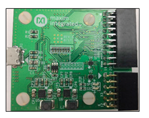
The USB2GPIO# design is powered directly from the USB bus power (5V) and integrates two low-power, 1.2A, PWM step-down DC-DC converters (MAX1556) to provide programmable VCC voltages of 1.8V, 2.5V, 3.3V, or 5.0V. A dual, high-speed, USB-to-multipurpose UART/FIFO IC (FT2232HQ), high-speed USB switches (MAX4983), and a 4K MICROWIRE-compatible serial EEPROM are the other ICs on this adapter board.

USB2GPIO# is designed to supersede USB2PMB1# and USB2PMB2# adapters and includes two connectors; connector X3 is a 12-pin connector which supports either I2C with 6 GPIO pins, or SPI with 4 GPIO pins, and is fully compatible with previous adapters and low-pin count EV kit or Pmod boards. This connector is controlled from the Munich GUI. The addition of another connector, X2, which is a 20-pin connector allows either 16 extra GPIO connections or a second SPI port and 12 extra GPIO connections. This 20-pin connector is NOT controlled by Munich GUI but is for use with future EV kits and will be controlled by the relevant EV kit GUIs.

This USB2GPIO# adapter board can be used to enable USB-to-I2C/SPI interface for any Pmod-compatible plug-in peripheral modules such as the Maxim MAX14001PMB#, and MAXREFDES12 – Corona reference designs. In addition, it can be ordered together as an evaluation system (EV system) with different EV kits, such as MAX14001EVKIT#. Note that an “EV system” is an EV kit combined with an interface board, such as a USB2GPIO# and EV kit GUI software. Ordering information for EV systems is included in the EV kits’ corresponding data sheet. Refer to the appropriate EV kit data sheet for quick start and detailed operating instructions.

The USB2GPIO# has been tested on Windows® 7, Windows 8, and Windows 10 system using Munich GUI, Version 2.17 or later.

Applications

  • Cell Phones/Smartphones
  • Digital Cameras and Camcorders
  • Handheld Instruments
  • PDAs and Palmtop Computers
  • Portable MP3 and DVD Players

MAX1556EVKIT

Evaluation Kit for the MAX1556 and MAX1557

Features and Benefits

  • Up to 97% Efficiency
  • 95% Efficiency at 1mA Load Current
  • 1MHz PWM Switching Frequency
  • Tiny Inductors
  • Pin-Selectable Output Voltages
    • MAX1556: 3.3V, 2.5V, 1.8V, and Adjustable
    • MAX1557: 1.5V, 1.3V, 1.0V, and Adjustable
  • 1.2A Guaranteed Output Current (MAX1556)
  • Voltage Positioning Optimizes Load-Transient Response
  • Low 16µA Quiescent Current
  • Low 27µA Quiescent Current in Dropout
  • Low 0.1µA Shutdown Current
  • Analog Soft-Start with Zero Overshoot Current
  • Small, 10-Pin, 3mm x 3mm TDFN Package
  • Fully Assembled and Tested

Product Details

The MAX1556 evaluation kit (EV kit) is a fully assembled and tested circuit board that evaluates the MAX1556 and MAX1557 PWM step-down DC-DC converters. The circuit operates from 2.6V to 5.5V. The MAX1556 delivers up to 1.2A and has pin-selectable 1.8V, 2.5V, 3.3V, and adjustable output. The MAX1557 delivers up to 600mA and has pin-selectable 1V, 1.3V, 1.5V, and adjustable output. Each circuit features an on-board shutdown control.

Applications

  • Cell Phones/Smartphones
  • Digital Cameras and Camcorders
  • Handheld Instruments
  • PDAs and Palmtop Computers
  • Portable MP3 and DVD Players

USB2GPIO
Evaluation Kit for the USB2GPIO
USB2GPIO: Board Photo
MAX1556EVKIT
Evaluation Kit for the MAX1556 and MAX1557

Latest Discussions

No discussions on max1557 yet. Have something to say?

Start a Discussion on EngineerZone®

Recently Viewed