LTM8051

RECOMMENDED FOR NEW DESIGNS

Quad 40VIN Silent Switcher μModule Regulator with Configurable 1.2A Output Array

Part Models
3
1ku List Price
Starting From $10.63

Part Details

  • Four Complete Step-Down Switching Power Supplies
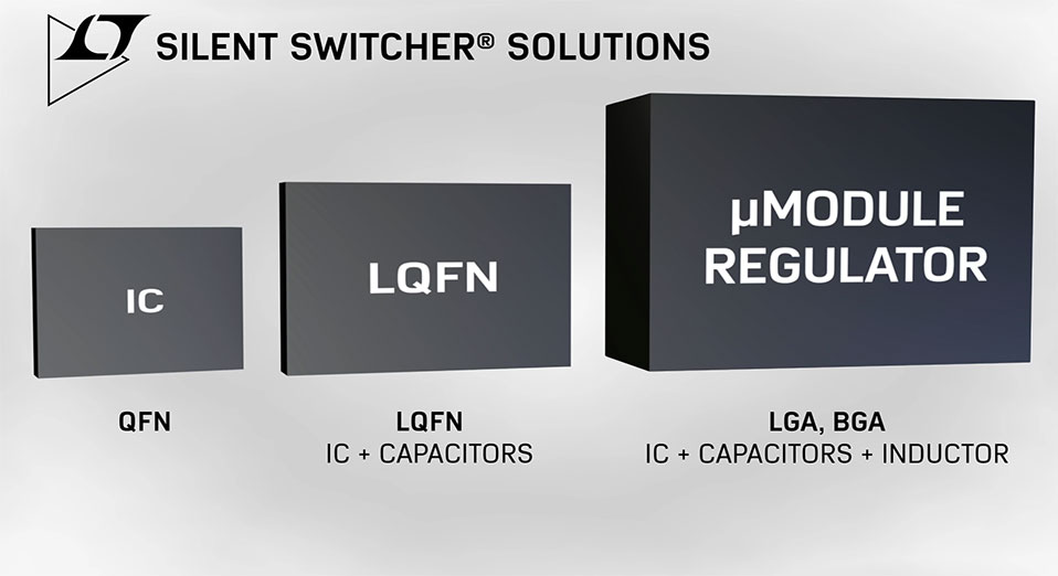
  • Low Noise Silent Switcher® Architecture
  • CISPR22 Class B Compliant
  • CISPR25 Class 5 Compliant
  • Wide Input Voltage Range: 3V to 40V
  • Wide Output Voltage Range: 0.8V to 8V
  • Selectable Switching Frequency: 300kHz to 3MHz
  • 1.2A Continuous Output Current per Channel at 12VIN, 3.3VOUT, TA = 85°C
  • 1.5A Continuous Output Current per Channel at 12VIN, 3.3VOUT, TA = 60°C
  • Multiphase or Multi-μModule Parallelable for Increased Output Current
  • Compact Package (6.25mm × 11.25mm × 2.22mm) Surface Mount BGA
LTM8051
Quad 40VIN Silent Switcher μModule Regulator with Configurable 1.2A Output Array
Ask a Question

Documentation

Learn More

Software Resources

Can't find the software or driver you need?

Request a Driver/Software

Tools & Simulations

LTspice 1


Models for the following parts are available in LTspice:

  • LTM8051
LTspice

LTspice® is a powerful, fast and free simulation software, schematic capture and waveform viewer with enhancements and models for improving the simulation of analog circuits.


Evaluation Kits

eval board
DC2860A

LTM8051 Demo Board | 40V, 1.2A Quad Step-Down Silent Switcher μModule Regulator

Product Details

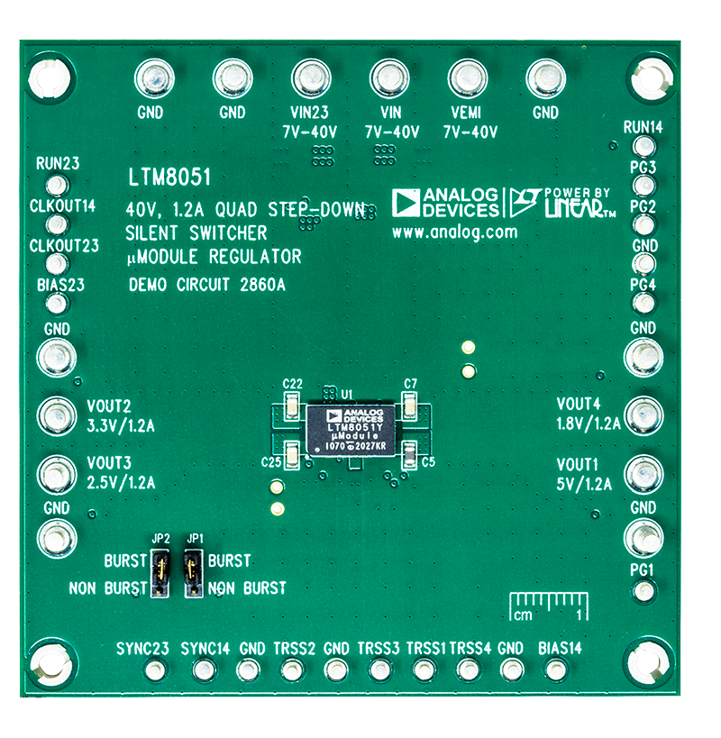
Demonstration circuit 2860A is a quad step-down DC/DC switching converter featuring the LTM8051 silent switcher μModule® regulator. The demo board is designed to deliver quad 5V/1.2A, 3.3V/1.2A, 2.5V/1.2A and 1.8V/1.2A outputs from a 7V to 40V input. The Silent Switcher® architecture minimizes EMI while achieving high efficiency at frequencies up to 3MHz. The modes of operation (Burst Mode® operation or discontinuous mode/SYNC) are jumper selectable. Burst Mode operation improves efficiency at light loads.

The LTM8051 is a fixed frequency PWM regulator with current mode control scheme. The switching frequency of channel 1 and channel 4 is set by an appropriate resistor (R11) from the RT14 pin to ground. The switching frequency of channel 2 and channel 3 is set by another appropriate resistor (R23) from the RT23 pin to ground. The RUN14 pin (RUN14 terminal) can be used to set the LTM8051 channel 1 and channel 4 in micro power shut-down mode, while the RUN23 pin (RUN23 terminal) can be used to set the channel 2 and channel 3 in shutdown mode. Output tracking and soft start pins (TRSS1/TRSS2/TRSS3/TRSS4) allow user control of output voltage ramp rate during startup. The power good output of each channel (PG1/PG2/PG3/PG4) will be low when that channel’s output voltage is outside of the ±7.5% regulation window.

The LTM8051 data sheet gives a complete description of the operation and application information. The data sheet must be read in conjunction with the demo manual.

DC2860A
LTM8051 Demo Board | 40V, 1.2A Quad Step-Down Silent Switcher μModule Regulator

Latest Discussions