How to Select Supply Topology for Processors, Microcontrollers, and High Power Devices
How to Select Supply Topology for Processors, Microcontrollers, and High Power Devices
摘要
This article provides a comprehensive guide on how to select the right power supply topology for processors, microcontrollers, and high power signal chains. It highlights the critical role of efficient and reliable power conversion in the signal chain and emphasizes the significance of these compact yet powerful devices across diverse electronic applications. Whether in consumer or industrial automation settings, these devices act as primary processing units, necessitating a stable and precisely regulated power supply for optimal performance. The guide underscores the importance of choosing a suitable power supply architecture to ensure seamless and optimal operation.
Introduction
This article will delve into the practical considerations of power supply topologies (low dropout (LDO) regulator, buck, boost, buck-boost, and single input multiple output (SIMO)). It will assess their applications, significance, benefits, and drawbacks. By providing practical insights, this evaluation aims to assist in making informed decisions during the design process.
The Importance of Core Voltage Stability
Before delving into the details of power supply topologies, it is crucial to understand the significance of maintaining core voltage stability for processors and microcontrollers.
- Performance: A stable core voltage ensures consistent and reliable performance of the device, preventing unexpected crashes, glitches, or erratic behavior.
- Power efficiency: Well-regulated core voltage minimizes power wastage, enhancing the overall energy efficiency of the system.
- Longevity: Voltage fluctuations can lead to premature wear and tear on the device, reducing its lifespan.
- Electromagnetic compatibility (EMC): Stable core voltage helps meet EMC standards by reducing electromagnetic interference (EMI), which is essential in sensitive applications like medical devices and aerospace systems.
- Noise immunity: Proper voltage regulation protects the device from external electrical noise, enhancing its reliability in noisy environments.
Common Power Supply Topologies
Commonly used power supply topologies for microprocessors and microcontrollers include linear regulators and switched-mode power supplies (SMPS) like buck, boost, buck-boost converters, and SIMO converters. Each topology has its own advantages and disadvantages. Let’s delve into these topologies to gain a thorough understanding.
Linear Regulator
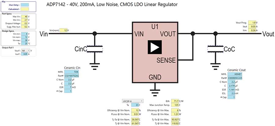
Linear regulators are simple and cost-effective solutions for low power applications. They work by dissipating excess voltage as heat, providing a constant output voltage regardless of input variations. However, they are inefficient for high current applications because of the power dissipation. Figure 1 shows a linear regulator.

There are many things to consider when designing with LDO regulators. Table 1 outlines the advantages and disadvantages.
| Advantages | Disadvantages |
| LDO regulators maintain stable output voltage even with input voltages close to the desired level, ensuring reliable performance with low input power. |
LDO regulators lose efficiency when the input and output voltages differ significantly, resulting in excess power being converted into heat. In such cases, switching regulators may be a more energy-efficient choice. |
| With minimal output noise, LDO regulators excel in applications demanding a clean and stable voltage supply, such as precision analog circuits and sensitive microcontrollers. |
LDO regulators have lower currenthandling capabilities compared to switching regulators, making them unsuitable for high power applications or those with heavy current demands. |
| LDO regulators simplify designs by requiring fewer external components compared to alternatives like switching regulators, resulting in a compact PCB footprint and reduced complexity. |
LDO regulators tend to generate heat due to power dissipation, especially in high power situations. Proper thermal management is crucial to prevent overheating. |
| Offering swift responses to load changes, LDO regulators are ideal for applications with dynamic conditions, such as microcontrollers and digital processors. |
LDO regulators require an input voltage higher than the desired output, limiting their use in battery-powered devices where the battery voltage is close to the desired output. |
| Ultralow quiescent current versions of LDO regulators enhance efficiency for battery-powered devices, minimizing standby power consumption. |
While LDO regulators can be cost-effective in many scenarios, they may not be the most budget-friendly choice for high current or high efficiency applications compared to switching regulators. |
| LDO regulators have excellent output voltage accuracy, making them wellsuited for applications requiring precise voltage regulation. |
If the input voltage is significantly higher than the desired output, LDO regulators may require additional components such as heat sinks or complex protection circuits to function effectively. |
Switched-Mode Power Supply (SMPS)
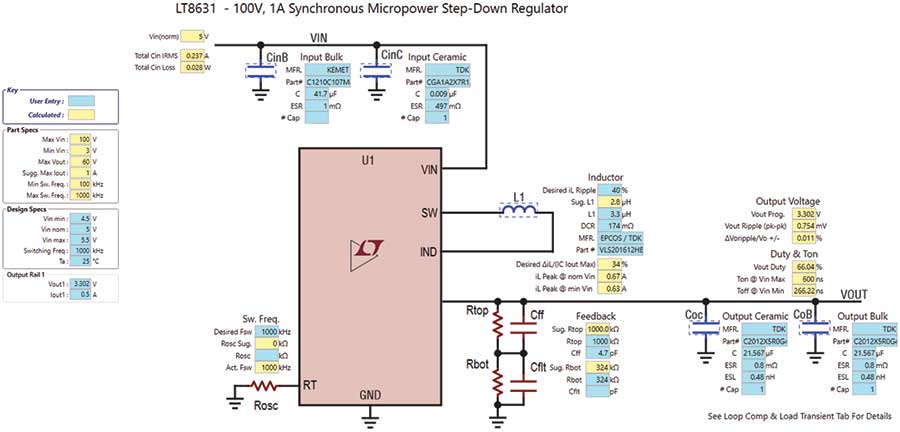
SMPS is the most commonly used topology for microprocessors and microcontrollers due to their high efficiency. An SMPS converts the input voltage to the desired output by rapidly switching the power devices (usually transistors) on and off. This allows for precise voltage regulation and minimizes power dissipation. Buck, boost, and buck-boost topologies are demonstrated in Figure 2.


When utilizing an SMPS, various factors should be considered, including both advantages and disadvantages. Table 2 outlines these important aspects.
| Advantages | Disadvantages |
| SMPS excels in efficiency, wasting less power as heat compared to linear regulators, making it an ideal solution for energy-efficient devices and those powered by batteries. |
Designing and implementing SMPS is more intricate than linear regulators, demanding extra components and advanced control circuitry. This complexity can raise development costs and pose reliability challenges. |
| With the ability to handle a broad input voltage range, SMPS is well-suited for applications dealing with fluctuating or unstable power sources. |
SMPS can result in EMI, impacting nearby components. As such, additional filtering and shielding measures are needed to mitigate potential issues. |
| Compact and lightweight, SMPS outshines linear power supplies in size and weight, making it a top choice for applications with critical constraints. |
Certain SMPS designs may exhibit higher output voltage ripple than linear regulators, posing a challenge for applications demanding ultralow noise levels. |
| Offering stable output voltage even with varying or inconsistent input, SMPS plays a vital role in powering electronic devices reliably. |
Despite its efficiency, SMPS can be pricier to manufacture and design due to the need for additional components and control circuitry. |
| SMPS boasts a quick transient response, making them the go-to for applications requiring swift adjustments to load changes. |
SMPS may not be a one-size-fits-all solution, particularly in scenarios where electrical noise or interference is a concern, or when a pristine DC output is essential. |
| Versatility is a key strength of SMPS, as it can be tailored to meet a wide range of output voltage and current requirements, catering to diverse applications. |
Some SMPS designs have limitations on the maximum current they can handle. For high power applications, larger and more complex SMPS systems may be necessary. |
| Generating minimal heat, SMPS is advantageous in applications where effective thermal management is a priority. |
Types of SMPS
Buck Converter
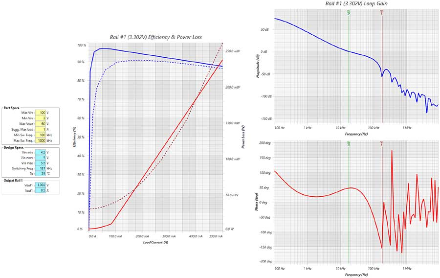
A buck converter is a specific type of SMPS that steps down the input voltage to a lower output voltage. It is widely used for powering microcontrollers and low power microprocessors. The buck converter operates by turning the switch (usually a transistor) on and off, storing energy in an inductor and capacitor, and then delivering it to the output in a regulated manner. Figure 3 depicts a buck converter utilized in a system-level solution to convert a high voltage rail to 3.3 V efficiently.

When opting for a buck converter as the power supply topology, it’s essential to weigh its advantages and disadvantages. Table 3 provides a summary overview of these key considerations.
| Advantages | Disadvantages |
| Buck converters are known for their high efficiency when converting higher input voltages to lower output voltages. They waste less energy as heat compared to linear regulators. |
Buck converters require complex control circuitry for proper operation, which can increase design complexity and the risk of potential reliability issues. |
| Thanks to their high efficiency, buck converters generate less heat, which is crucial for applications where thermal management is a concern. |
Buck converters can generate EMI due to the switching action, which may require additional filtering and shielding measures. |
| Buck converters are typically smaller and lighter than linear regulators, making them suitable for applications with size and weight constraints. |
Some buck converter designs may have a higher output voltage ripple compared to linear regulators. This can be a concern for applications that require very low noise levels. |
| Buck converters can handle a broad input voltage range, allowing them to work well with variable or unstable power sources. |
Buck converters can only step down the input voltage, and they are not suitable for applications that require a higher output voltage than the input voltage. |
| Buck converters have a fast transient response, making them suitable for applications that require rapid adjustments to changes in load conditions. |
Some buck converter designs have limitations in terms of the maximum current they can handle. High power applications may require more complex buck converter configurations. |
| Buck converters provide a stable and well regulated output voltage, even when the input voltage fluctuates. |
The design and selection of components for a buck converter can be challenging and may require careful consideration of factors such as inductor selection, switching frequency, and control loop design. |
| Buck converters are commonly used in battery-powered devices where energy efficiency is critical. They help extend battery life by minimizing power losses. |
SIMO Converter
SIMO is an innovative power management technique that provides multiple regulated voltage outputs from a single inductor.2 Traditional power management circuits typically require a separate inductor for each output, leading to increased component count, board space, and energy losses. SIMO simplifies this by using a single inductor shared between multiple output channels, improving efficiency, and reducing the overall footprint. A SIMO design used to power up multiple output rails is illustrated in Figure 4.


When employing the SIMO converter as a power supply topology, it’s important to consider various factors. Table 4 concisely outlines the advantages and disadvantages of this choice.
| Advantages | Disadvantages |
| SIMO technology boosts power efficiency by sharing a single inductor among multiple outputs, cutting energy losses—a win for battery-powered devices. |
Implementing SIMO brings complexity in control and regulation compared to traditional power solutions. Achieving stability and reliability for multiple outputs demands meticulous design and control circuitry. |
| Using just one inductor for multiple outputs, SIMO trims down the PCB footprint, a major plus for compact and space-limited applications. |
SIMO usually supports a limited number of output channels due to sharing a single inductor, making it less suitable for applications needing numerous voltage levels. |
| With fewer components and simpler circuitry, SIMO brings cost savings in manufacturing, reducing the risk of faults and enhancing device reliability. |
SIMO designs may struggle to swiftly respond to rapid load changes, as the shared inductor adjusts to diverse output voltage requirements. |
| Thanks to improved efficiency, SIMO designs generate less heat, keeping operating temperatures cooler and potentially extending device lifespan, without the need for complex thermal management. |
Engineers face a delicate balance in SIMO designs, weighing the number of output channels, efficiency, and component count. Navigating this trade-off for a specific application can be a challenge. |
| SIMO technology crafts compact and energy-efficient power solutions, making it perfect for wearables, IoT devices, and smartphones. |
Adapting existing devices to SIMO technology may require substantial redesign and redevelopment, posing potential hurdles for seamless integration. |
Boost Converter
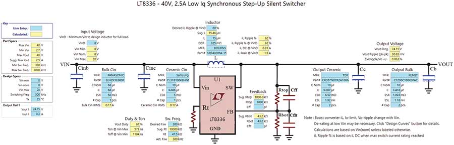
A boost converter is a power supply topology that steps up the input voltage to a higher output voltage. While less common for microcontrollers and microprocessors, boost converters find use in applications where a higher core voltage is needed. In Figure 5, a boost converter is used to provide a 24 V output rail of a high voltage precision amplifier.

When opting for a boost converter as your power supply topology, it’s crucial to consider several factors. Table 5 provides a clear overview of the advantages and disadvantages associated with this choice.
| Advantages | Disadvantages |
| Ideal for high voltage applications: Boost converters are well-suited for applications that require a higher output voltage than the input voltage. |
Less efficient than buck converters: Boost converters typically have lower efficiency compared to buck converters, as they need to step up the voltage. |
| Efficiently boosts input voltage: Boost converters can efficiently increase the input voltage to the desired output voltage level. |
Not recommended for battery-powered devices that prioritize energy efficiency: Boost converters may not be the best choice for battery-powered devices that prioritize energy efficiency, as they consume more power and may drain the battery faster. |
Buck-Boost Converter
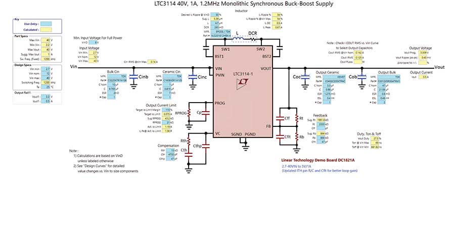
The buck-boost converter combines the capabilities of both buck and boost converters, allowing it to step down or step up the input voltage to provide a regulated output voltage. This flexibility makes it a versatile choice for applications with varying voltage requirements. For example, in Figure 6, a buck-boost converter is used to regulate the output voltage from a battery cell stack that can have varying input voltages. Once the battery stack is in charge operation (the input voltage is roughly around 4.5 V to 5 V while in discharge operation) the battery cell voltage may drop to 1.5 V to 2.7 V, therefore a buck-boost converter is required for this type of application.


When using a buck-boost converter as your power supply architecture, you must consider several factors. Table 6 briefly summarizes the benefits and drawbacks of this option.
| Advantages | Disadvantage |
| Versatile for various input and output voltages: The buck-boost converter can handle a wide range of input and output voltages, making it suitable for applications with different power requirements. |
Moderately complex compared to simpler converters: The buck-boost converter is more complex than simpler converter topologies like the buck or boost converter. This complexity may require additional design considerations and careful component selection. |
| Ideal for battery-powered devices, working from a single power source: Since the input voltage can vary significantly in battery-powered devices, the buck-boost converter can efficiently regulate the output voltage regardless of the battery’s charge level. |
|
| Works from a single power source: The buck-boost converter can operate from a single power source, making it suitable for applications where only one power supply is available. |
Factors to Consider When Choosing a Topology
Selecting the right power supply topology for your microprocessor or microcontroller depends on various factors. Here are some key considerations:
- Power efficiency: Determine the power requirements of the device and choose a topology that offers high efficiency to minimize energy consumption and heat generation.
- Input voltage range: Consider the range of input voltages the device may encounter in its operating environment. Ensure that the chosen topology can accommodate these variations.
- Output voltage: Determine the required core voltage for the microprocessor or microcontroller. Some topologies, like buck-boost converters, are more flexible in this regard.
- Size and weight constraints: If the application has space or weight limitations, choose a topology that offers a compact and lightweight solution.
- Cost: Evaluate the cost constraints of the project. While linear regulators may be cost-effective for low power applications, SMPS solutions might be more cost-efficient for higher power requirements.
- EMC considerations: If the application requires compliance with EMC standards, ensure that the chosen topology can meet these requirements through proper layout and filtering.
- Transient response: Consider the transient response of the power supply. Microprocessors and microcontrollers often experience sudden changes in load, and topology with a fast and stable response is essential to prevent voltage droop or overshoot.
- Reliability: Assess the reliability requirements of the application. Some topologies, like linear regulators, have fewer components and may be more reliable in certain scenarios.
- Environmental conditions: Take into account the operating environment of the device. For battery-powered applications, energy efficiency is crucial, while for industrial applications, robustness, and noise immunity may be more critical.
Practical Tips for Implementation
Once you have selected the appropriate power supply topology, here are some practical tips for successful implementation:
- Component selection: Choose high quality components, including inductors, capacitors, and transistors, to ensure stable and reliable operation.
- Layout and routing: Pay careful attention to the layout and routing of the power supply circuitry on your PCB. Minimize loop areas and use proper grounding techniques to reduce noise and improve EMC performance.
- Filtering: Incorporate input and output filters as needed to suppress EMI and ensure a clean and stable output voltage.
- Protection: Implement overvoltage, undervoltage, and overcurrent protection mechanisms to safeguard the microprocessor or microcontroller from potential damage.
- Testing and characterization: Thoroughly test and characterize your power supply circuit under various operating conditions to ensure it meets the desired performance specifications.
- Heat management: If the design involves power dissipation, consider adding heat sinks or thermal management solutions to prevent overheating.
Conclusion
Choosing the right power supply topology for a microprocessor or microcontroller is a crucial step in the design process. Each topology offers a unique set of advantages and disadvantages, and the decision should be based on the specific requirements of your application. Factors such as power efficiency, input voltage range, and output voltage stability should be considered to make an informed choice that ensures the reliable and efficient operation of the device.
However, it’s important to note that the implementation phase is equally important. Proper component selection, careful layout and routing, and thorough testing are essential to realizing the full potential of a chosen power supply topology. By paying attention to these details, microprocessors and microcontrollers can be powered effectively, enabling them to perform at their best in a wide range of applications.
References
“An Introduction to Switch-Mode Power Supplies.” Maxim’s Engineering Journal, Vol. 61, September 2007.
Cary Delano and Gaurav Mital. “SIMO Switching Regulators: Extending Battery Life for Hearables and Wearables.” Maxim Integrated (Now Analog Devices, Inc.), November 2017.
关于作者
关联至此文章
{{modalTitle}}
{{modalDescription}}
{{dropdownTitle}}
- {{defaultSelectedText}} {{#each projectNames}}
- {{name}} {{/each}} {{#if newProjectText}}
-
 {{newProjectText}}
{{/if}}
{{newProjectText}}
{{/if}}
{{newProjectTitle}}
{{projectNameErrorText}}
最新视频 21


