LTE-Advanced Release-12 Shapes New eNode Transmitter Architecture: Part 2, Analog Integration Challenge
Read other articles in this series.
摘要
Analog integration plays an important role in addressing new challenges faced by LTE-Advanced radio engineers. The 3rd Generation Partnership Project (3GPP) is working on Release 12 (Rel-12) of the LTE-Advanced standard. 3GPP Rel-12 includes many enhancements to 4G radio access technology including wideband carrier aggregation, multi-layer spatial multiplexing and advanced antenna configurations. The Rel-12 enhancements will challenge radio designers to integrate more RF transmitter channels that will enable smaller, lower power and higher performance eNodeB base stations. Advancements in RF analog integration and disruptive radio architectures can help engineers successfully overcome the integration challenge.
Introduction
This two-part application note series reviews new developments in the Fourth Generation Long Term Evolution (4G-LTE) cellular standard. The series explores LTE-Advanced (LTE-A) Release-12 (Rel-12) features and the impact on eNodeB radio frequency (RF) transmitters. The application notes reveal how analog integration can overcome design challenges arising from the latest 4G developments. A Glossary of Technical Terms is appended to the end of each application note.
The Part 1 application note on Technology Evolution examines market forces driving global adoption of the LTE standard and trends in fourth-generation (4G) radio access technology. Readers will learn about work items outlined in the 3rd Generation Partnership Project (3GPP) Rel-12 specification. Topics include carrier aggregation (CA), downlink spatial multiplexing, and active antenna systems (AAS).
Part 2, this application note, explores the analog integration challenges in 4G base stations. Rel-12 features such as wideband downlink carrier aggregation, downlink multiple-input multiple-out (MIMO) spatial multiplexing, and AAS with embedded RF, present new design challenges in next-generation eNodeB radios. A disruptive bits-to-RF solution is introduced that can help engineers shape alternative radio transmitter architectures. The discussion focuses on novel RF digital-to-analog converter (RF-DAC) technology that yields a single-chip, wideband RF transmitter solution. Readers will learn about system-level applications of the RF-DAC and the integration benefits that it delivers to eNodeB radio design.
Overview
A few salient points about the background of LTE and LTE-A Rel-12 must be summarized from the Part 1 application note. This short digression will be the best way to orient readers with design challenges arising from the latest 4G developments.
LTE is recognized as the fastest growing mobile broadband technology and becoming the most widely adopted cellular standard worldwide. LTE's global rate of adoption by wireless service providers has exceeded prior 2G and 3G deployments. The popularity of LTE is mainly due to its high spectral efficiency and high peak data rates, low-latency IP-based network, and evolutionary roadmap. But LTE is not "true 4G" service and is technically still considered 3.9G.
The "true 4G" radio communication standard, known as International Mobile Telecommunications-Advanced (IMT-Advanced), must meet the requirements set forth by the International Telecommunication Union Radio Sector (ITU-R). IMT-Advanced defines 4G as a service that delivers 100Mbps peak data rates for high-mobility users, and 1Gbps peak data rates for low-mobility clients. To comply with the IMT-Advanced vision, the 3GPP has developed many enhancements since the initial LTE Rel-8 standard published in 2008.
In Rel-10 the 3GPP introduced LTE-Advanced as "true 4G" service to meet or exceed the IMT-Advanced requirements. Presently, Rel-12 is close to introduction with a functional freeze date planned for March 2015. Figure 1 illustrates LTE development timelines, where it can be seen that theoretical peak downlink (DL) and uplink (UL) data rates have increased about 10x and 20x, respectively, from DL = 300Mbps/UL = 75Mbps in Rel-8 to DL = 3Gbps/UL = 1.5Gbps in Rel-10. The extraordinary increase in peak data rates is due, in part, to wideband CA complimented by multilayer spatial multiplexing introduced in Rel-10 and now an important part of Rel-12 enhancements.
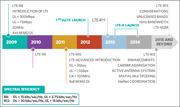
Figure 1. LTE release timeline showing evolutionary advancements in radio access technology.
Rel-12 enhancements will significantly impact how evolved NodeB (eNodeB) radios are designed. Some of the important Rel-12 items include new combinations of carrier aggregation, spatial multiplexing enhancements with downlink MIMO, and RF requirements needed in AAS. Figure 2 summarizes some of the Rel-12 items with respective features and benefits. The Rel-12 feature enhancements bring many benefits to the LTE ecosystem, along with new radio design and radio architecture challenges.
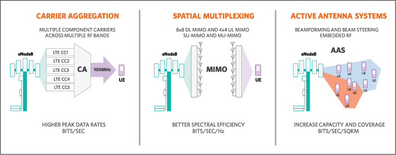
Figure 2. The features and benefits of Release-12 work items.
The RF Transmitter Integration Challenge in Macro Base Stations
In 4G macro cell base stations the adoption of downlink MIMO with multilayer spatial multiplexing or the deployment of AAS with embedded RF can increase transmitter channel density up to a factor of eight or sixteen, respectively compared to 2G/3G base stations. In the near future with multicolumn 3D antenna arrays, the radio channel count might increase to 32 or more per sector. Compounding the eNodeB channel density trend is a requirement for wideband frequency-agile transmitters. A common hardware eNodeB radio platform must support LTE band coverage from 450MHz to 2.2GHz with a roadmap for Band-7/Band-41 coverage, and support up to 100MHz of CA bandwidth. Clearly, a technology disruption is needed to facilitate integration of multichannel, high-performance radio transmitters into space-constrained, power-limited, and cost-sensitive applications like remote radio units, integrated antenna radios, AAS, and conventional base transceiver station (BTS) line cards.
The RF DAC Transmitter Solution
Direct bits-to-RF conversion with a high-speed RF DAC is a technology disruption for eNode transmitters. The RF-DAC partition uses direct digital synthesis (DDS) to move the quadrature modulator, agile local oscillator, and signal-filtering analog functions into the digital domain (Figure 3). The RF DAC with DDS partition leverages Moore's Law. It capitalizes on the fact that digital processes scale better than analog in terms of lower power consumption, faster speed, smaller die area, and lower cost. However, the benefits of Moore's Law can only be realized if direct signal conversion, from the digital domain to analog domain, is achievable. The RF DAC is the enabling technology that makes this possible because it bridges the digital-to-analog domain. An RF DAC is generally characterized as a mixed-signal device that operates in multiple Nyquist zones with conversion rates above 1.5Gsps to perform direct bits-to-RF signal synthesis. An RF DAC synthesizes output signals of at least 500MHz signal bandwidth at carrier frequencies of 2.0GHz or higher.
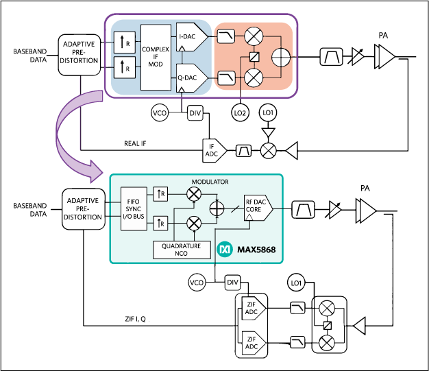
Figure 3. Diagram shows the RF transmitter architecture moving from a conventional complex-IF lineup (top) to a single-chip RF DAC solution (MAX5868, bottom).
Benefits of the RF DAC Transmitter
Compared to conventional RF transmitter architectures (Figure 4) like zero intermediate frequency (Zero-IF), complex-IF and real-IF, the RF-DAC architecture solution occupies less printed circuit board (PCB) area with fewer Bill-of-Material (BOM) components. It operates at lower power and delivers excellent dynamic performance.
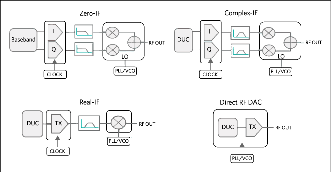
Figure 4. RF transmitter architecture options.
In terms of RF performance, the RF DAC has significant benefits versus other topologies. The digital upconversion (DUC) with digital filtering implemented in DDS eliminates gain-phase errors and achieves perfect carrier suppression with no LO leakage. The result is excellent EVM performance when transmitting high-order modulation like QAM64. The quadrature NCO makes the RF DAC an agile transmitter capable of tuning across the entire spectrum of LTE bands. Since the RF DAC is broadband and frequency agile with high dynamic range, a single device can synthesize multicarrier, multiband, and multistandard signals including GSM, WDMA, and LTE. Now designers can realize a fully digital software-defined radio and use common hardware across multiple eNodeB radio platforms.
Another benefit with direct-conversion RF-DAC technology is that it allows engineers to use a lower cost digital predistortion (DPD) observation receiver. Macro cell base stations use DPD techniques for RF power amplifier (PA) linearization. This requires a PA observation receiver channel, like that shown in Figure 3, to monitor the PA output. The observation receiver detects PA distortion products and works with a predistorter to compensate for intermodulation and adjacent-channel leakage power. Typically, DPD bandwidth expansion requires the DPD observation receiver bandwidth to be five times the data bandwidth. In 100MHz CA applications this means that the DPD bandwidth must be at least 500MHz. Also, the observation receiver cannot add impairments to the observed signal because they cannot be discerned from the main TX path impairments. Consequently, the DPD observation path must have excellent linearity which adds cost and circuit complexity. Conversely, if the main TX path has negligible impairments, then the DPD path impairments can be corrected.
Recall that the RF-DAC does not introduce gain or phase errors, thus resulting in negligible TX path impairments. Therefore, a low-cost and lower performance DPD receiver like a zero intermediate frequency (ZIF) receiver can be employed. There are three reasons why the ZIF architecture is lower cost compared to high-IF or direct-RF sampling: (1) quadrature demodulation enables a lower conversion rate, baseband-sampling, dual-channel high-speed ADC because it only needs to quantize one-half the DPD expansion bandwidth; (2) the ADC samples baseband signals, not high-IF or direct RF, which means that the ADC does not need pico or femto second aperture jitter; and (3) the baseband I/Q anti-alias filters are lower cost and easier to design compared to IF or RF filters. In summary, the RF-DAC transmitter relaxes DPD receiver signal-path performance requirements; thus further reducing system cost and design complexity.
RF-DAC in MIMO Applications
LTE Rel-8 established support for 2x2 MIMO in user equipment (UE) categories 2 thru 4. The UE category indicates user device's capability for an achievable data rate. Rel-8 also introduced 4x4 MIMO to realize downlink spectral efficiency of 15 bits/sec/Hz and deliver a peak data rate of 300Mbps. Rel-10 extended this with 8x8 MIMO to attain 30 bits/sec/Hz efficiency and 3Gbps downlink data rate. Rel-12 introduces further enhancements for MIMO antenna schemes.
MIMO adoption can be considered an eNodeB radio transmitter channel multiplier. Note that 8x8 MIMO has double the radio channel density of 4x4 MIMO, and four times the density of 2x2 MIMO. This can be called the "MIMO multiplier effect." As 4G networks evolve to support multiple antenna configurations, the number of MIMO transmitter channels will multiply. The MIMO multiplier effect makes circuit size a critical design factor for eNodeB transmitters.
Figure 5 compares the PCB area of a typical zero-IF transmitter with an RF DAC transmitter in a 2X2 MIMO application. The RF DAC lineup is a significantly smaller solution; it typically occupies 60% less PCB area and reduces component count by 75%. The RF DAC enables designers to increase radio transmitter channel density without increasing PCB area. With its integration, it cuts BOM cost and reduces inventory. Also, this low-component-count solution minimizes the number of IC interconnections which, in turn, reduces trace routing complexity and relaxes component placement requirements. Designers will gain PCB layout flexibility, better likelihood of first-time design success, faster time-to-market with shorter design time, and higher reliability from fewer points of potential failure.
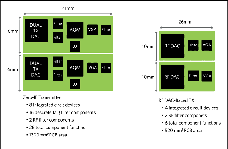
Figure 5. A PCB area comparison between a 2x MIMO zero-IF transmitter and the MAX5868 RF DAC transmitter. Note that: AQM = analog quadrature modulator; LO = local oscillator (PLL/VCO synthesizer); VGA = variable gain amplifier; I/Q filters = multipole, differential. Diagram is not to scale.
As described above and illustrated in Figure 5, the RF-DAC benefits are impressive in a 2x2 MIMO application. Applying the "MIMO multiplier effect" in an 8x8 MIMO application reveals substantial benefits with the RF-DAC architecture. An RF-DAC transmitter is unmatched in achieving this level of PCB area reduction, making it the ideal MIMO transmitter solution for eNodeB applications.
RF DAC for Downlink Carrier Aggregation
A single RF DAC transmitter can synthesize five 20MHz component carriers in one band or across multiple bands, supporting either intraband or interband CA. Figure 6 illustrates a 40MHz interband Rel-12 CA scenario with the RF DAC synthesizing two 20MHz component carriers, one at Band-1 (2110MHz to 2170MHz) and another at Band-3 (1805MHz to 1880MHz). In this CA application a single RF DAC simultaneously synthesizes component carriers anywhere within the 60MHz Band-1 and 75MHz Band-3 spectra. Because the RF DAC is ultra-wideband, the RF output spans the entire 365MHz interband separation from 1805MHz to 2170MHz.
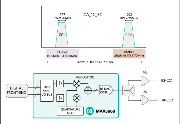
Figure 6. A carrier aggregation scenario where the MAX5868 RF DAC simultaneously synthesizes two 20MHz component carriers with 365MHz carrier separation.
Conventional architectures like those described earlier (i.e., ZIF, complex-IF, and real-IF) cannot provide this level of broadband performance with a single device. For example, a conventional narrowband transmitter supporting the interband noncontiguous CA scenario described in Figure 6 (CA_1C_3C) requires two complete RF signal-path lineups. Each signal path comprises multiple RFIC devices with filtering. And each signal path is dedicated to an individual component carrier (CC1 and CC2). The penalty is double the number of devices and larger PCB footprint.
Alternatively for example, a conventional wideband real-IF transmitter requires only one RF signal-chain lineup but comprises multiple devices: a high-IF DAC, IF filter, mixer preamp, upconverting mixer, and LO synthesizer. Further, coverage across all LTE bands becomes a design hurdle due to wideband mixer linearity requirements. The real-IF lineup must use band-specific mixers to cover the LTE bands from 460MHz to 2.2GHz, or use a single power-hungry wideband mixer with ultra-high linearity. Either approach requires more hardware and occupies more PCB area than the RF-DAC solution.
Consequently, for downlink CA applications the important system-level benefits of a wideband RF DAC transmitter include: LTE band coverage up to 2.2GHz, significantly fewer IC devices, no IF or baseband analog filters, and a footprint that occupies the smallest possible PCB area.
An RF DAC AAS Design Example
A case study highlights a typical RF DAC transmitter application in an AAS design. As described earlier, AAS with embedded RF dedicate a radio transceiver to each cross-polarized antenna element. A dual-column, side-by-side antenna array with 16 cross-polarized elements is used as an example. There are a total of 16 dual-channel RF transceivers (2T2R) with DPD (2DPD) as shown in Figure 7.
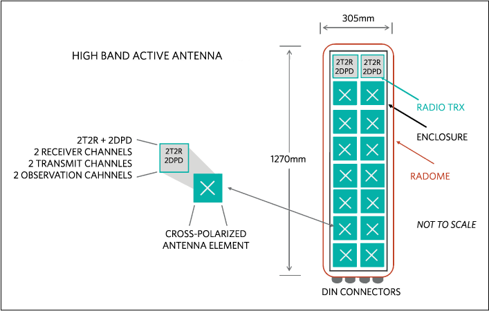
Figure 7. Assembly diagram showing dimensions of an active antenna system comprising an array of 16 cross-polarized antenna elements.
The TX signal path in each transceiver has its own RF PA, typically 5W, for a total power output of 80W. A high-band antenna measures 305mm (W) x 1270mm (L) x 178mm (D). The available area for electronics inside the antenna is less than 2062 square centimeters. After allowing for mechanical clearance, each of the 16 transceivers (including its power management, all measurement/control functions and RF duplexers) needs to occupy a PCB area of approximately 130 square centimeters (Figure 8).
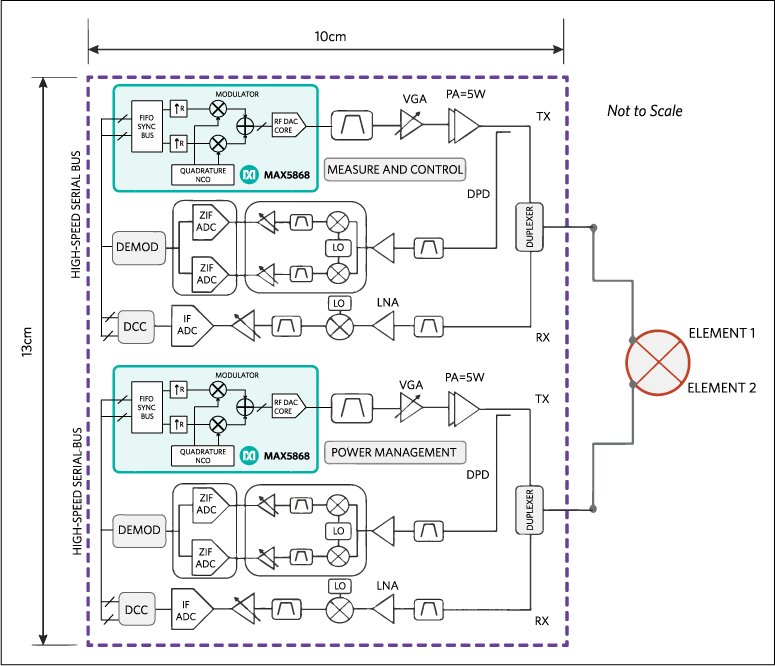
Figure 8. Each AAS radio transceiver (2T2R+2DPD) must occupy about 130 square centimeters.
Essentially a complete 2T2R+2DPD eNodeB radio transceiver must shrink to half the size of a typical shoebox. To overcome this size constraint, its obvious dense RF integration is a key design parameter in next-generation AAS radios. Furthermore, in AAS applications power consumption and heat dissipation become critical because the RF transceiver channel count is high, the antenna units are passively cooled, and the system is exposed to high-ambient outdoor temperatures. An RF DAC transmitter is approximately 1W less power than conventional architectures. Since the antenna has 32 physical transmitter channels, a power savings of 1W per TX channel sums to 32W power savings per antenna system. This power savings and reduced heat dissipation is important in outdoor tower-mount AAS installations where compact size and high reliability are critical. For AAS applications the RF DAC transmitter yields significant power savings and considerable size reduction while delivering all the previously described system-level benefits.
Conclusion
Over the next five years the volume of mobile data traffic and number of mobile broadband users is expected to grow exponentially. New bandwidth-hungry mobile services like multimedia broadcast, HD video, and file sharing will escalate demand for higher peak data rates. But available cellular spectrum is both limited and a valuable resource that must be utilized efficiently. Further, to stay competitive mobile network operators must offer the highest quality-of-experience service at the lowest cost per bit. For long-term profitability it is clear that LTE-Advanced is the wireless service provider's investment of choice. The radio access technologies outlined in 3GPP Rel-12 address the peak data rates, spectrum utilization, and network efficiency that service providers need to sustain 4G mobile broadband demand. However, wideband CA, AAS with embedded RF, and high-order downlink MIMO present new integration challenges to eNodeB radio designers.
RF analog integration is essential for overcoming radio integration challenges in 4G base stations. The new RF DAC direct-conversion transmitter is a technology disruption that diverges from conventional solutions; it gives radio engineers the means to shape alternative eNode transmitter architectures. Compared to conventional RF transmitters, an RF DAC like the MAX5868 reduces system cost and complexity, occupies less PCB area, consumes lower power, and delivers ultra-wideband performance with LTE band coverage up to 2.2GHz. To successfully deploy LTE-Advanced Rel-12 features each parameter is critical for next generation eNode transmitters.
| 2G, 3G, 4G | Generations |
| 3GPP | 3rd Generation Partnership Project |
| 4G-LTE | 4th Generation Long Term Evolution |
| AAS | Active Antenna System |
| ACLR | Adjacent-Channel Leakage Ratio |
| ARPC | Average Revenue Per Connection |
| ARPU | Average-Revenue-Per-User |
| BTS | Base Transceiver Station |
| CA | Carrier Aggregation |
| CAGR | Compounded Annual Growth Rate |
| CAPEX | Capital Expenditure |
| CC | Component Carrier |
| CSI | Channel State Information |
| DCI | Downlink Control Information |
| DL | Downlink |
| DL-CA | Downlink Carrier Aggregation |
| DM RS | Demodulation Reference Signal |
| DPD | Digital Predistortion |
| DUC | Digital Upconversion |
| eNodeB | Evolved Node B |
| FD-MIMO | Full-Dimension MIMO |
| IAR | Integrated Antenna Radio |
| IMT-Advanced | International Mobile Telecommunications-Advanced |
| ITU-R | International Telecommunication Union Radio Sector |
| LTE | Long Term Evolution |
| LTE-A | LTE-Advanced |
| MIMO | Multiple Input/Multiple Out |
| PCB | Printed Circuit Board |
| RF | Radio Frequency |
| Rel-12 | Release 12 |
| ROI | Return On Investment |
| RRU | Remote Radio Unit |
| TCO | Total Cost of Ownership |
| TM9 | Transmission Mode 9 |
| TX | Transmitter |
| UE | User Equipment |
| UL | Uplink |
| Zero-IF | Zero Intermediate Frequency |
| ZIF | Zero Intermediate Frequency |
A similar version of this article appeared March 20, 2015 in EDN.
{{modalTitle}}
{{modalDescription}}
{{dropdownTitle}}
- {{defaultSelectedText}} {{#each projectNames}}
- {{name}} {{/each}} {{#if newProjectText}}
-
 {{newProjectText}}
{{/if}}
{{newProjectText}}
{{/if}}
{{newProjectTitle}}
{{projectNameErrorText}}
最新视频 21


