概览
描述
MAXREFDES278#是一款完整的IO-Link® 8通道电磁阀执行器参考设计,基于MAX22514 IO-Link收发器,提供集成保护。该设计展示了使用MAX22200 1A八通道集成式串行控制电磁阀驱动器和集成FET的八通道电磁阀执行器。该参考设计可以采用两种电源,可以通过IO-Link主机直接供电,提供高达800mA总负载,或者使用外部电源供电,实现更高的电流。为了确保电流不会回流至IO-Link主机,且IO-Link部分始终带电,该设计使用MAX17608限流器来提供过压(OV)、欠压(UV)和反向保护。
MAXREFDES278#采用工业封装,尺寸仅为85mm x 42mm,采用工业标准型M12连接器,同时支持使用4线IO-Link电缆。每个电磁阀通道都包含双向端子块。
在此设计中,MAX22200八通道电磁阀驱动器和MAX22514 IO-Link器件收发器之间连接有一个STM32低功耗微控制器。MAX22514采用集成式浪涌保护,在小型印刷电路板(PCB)中实现可靠通信,无需使用外部保护组件,例如瞬态电压抑制器(TVS)二极管。MAX22514采用微型25引脚晶圆级封装(WLP)和24引脚TQFN封装,使MAXREFDES278#能够实现小尺寸。该设计利用MAX22514的集成式有源反向极性保护实现反向极性保护功能。MAX22514包括一个集成式DC-DC转换器和两个集成式低压降(LDO)稳压器(3.3V和5.0V)。DC-DC转换器用于为微控制器和MAX22200逻辑电源生成3.3V电源,能够降低散热和减少所需的外部组件数量,帮助节省空间和成本。MAX22514还采用低导通电阻C/Q驱动器来降低功耗,使该参考设计功耗非常小,散热量非常低。
这款IO-Link从站利用Technologie Management Gruppe Technologie und Engineering (TMG TE) IO-Link从协议栈与任何IO-Link 1.1版兼容主机通信。该电路板包含M12连接器,可使用标准M12电缆连接到兼容的IO-Link主站。将MAXREFDES278#连接到USB IO-link主机,例如 MAXREFDES165# 或 MAXREFDES145#,使用相关软件来实现轻松评估。
在“设计资源”选项卡下可找到设计文件和软件。该板同时有售。参考设计文件描述了上方所示的硬件。
应用
- 工业自动化
- 驱动器模块
- PLC和DCS系统
- 智能驱动器
优势和特点
- 符合IEC 61131-9标准
- TMG TE IO-Link堆栈
- 兼容IO-Link 1.1版
- 八通道电磁阀驱动器
详情
Advanced factory automation solutions (i.e., Industry 4.0) require an increasing number of smart sensors and actuators, which are typically controlled using IO-Link point-to-point serial communication between the sensor/actuator and controller (master). Maxim Integrated as a leading provider of IO-Link device transceiver and master transceiver ICs, also provides the complete reference design solutions to help its customers to improve their time to market. These proven designs cover all the hardware and software requirements needed for compliance with the IO-Link standard.
IO-Link is the first open, field bus agnostic, low-cost, point-to-point serial communication protocol used for communicating with sensors and actuators that has been adopted as an international standard (IEC 61131-9). IO-Link finally standardizes interoperability of industrial equipment from all over the world. IO-Link can function directly from the PLC or be integrated into all standard field buses, quickly making it the de-facto standard for universally communicating with smart devices such as the MAXREFDES278#.
With this reference design, IO-Link allows the user to program and diagnose 8 individual solenoids. This enables industrial actuator equipment original equipment manufacturers (OEMs) to provide end users with total flexibility at the factory floor level to simplify equipment installation and commissioning, while reducing their number of SKUs and BOMs and simplifying and streamlining their purchasing and manufacturing.
Maxim Integrated and TMG TE collaborated to design the MAXREFDES278# reference design compliant with the IO-Link version 1.1/1.0 standard. The MAXREFDES278# design has an industry-standard MAX22514 IO-Link device transceiver, a low-power microcontroller that uses the TMG TE IO-Link device stack, and a MAX22200 octal solenoid driver that is fully software configurable. The complete reference design fits on an 85mm x 42mm PCB; the size is mostly dominated by the connectors. Components are placed on the top-side only, for lower assembly cost.
Figure 2 shows the MAXREFDES278# system block diagram.
Figure 2. MAXREFDES278# system block diagram.
The MAXREFDES278# IO-Link octal solenoid driver consumes minimal power, and space, making it a complete solution for many actuators found in various industrial control and automation applications.
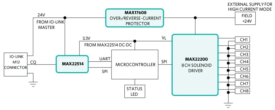
The MAX22514 IO-Link device transceiver is compliant with the IO-Link version 1.1/1.0 physical-layer specification. It integrates the high-voltage functions commonly found in industrial sensors and actuators, including drivers, and two linear regulators. The MAX22514 features extensive integrated protection to ensure robust communication in harsh industrial environments. All three I/O pins (V24, C/Q, and GND) are reverse-voltage and short-circuit protected and feature integrated ±1kV/500Ω surge protection. This enables a very small PCB area with no required external protection components, such as TVS diodes. The low on-resistance driver (C/Q) further reduces power dissipation so that this reference design consumes minimal power with very low thermal dissipation. Operation is specified for normal 24V supply voltages up to 36V. Transient protection is simplified due to high voltage tolerance (i.e., 65V absolute maximum rating for the I/O pins without the integrated TVS diodes) in addition to the integrated surge protection.
The integrated DC-DC regulator in the MAX22514 generates the 3.3V supply for the microcontroller as well as the MAX22200, reducing the number of additional external components and the required space.
The MAX22514 features high configurability as well as diagnostics through an SPI interface and a 3-wire UART interface is provided for IO-Link communication.
The MAXREFDES278# does not require external protection devices such as varistors or TVS diodes due to the integrated surge protection in the MAX22514 at the IO-Link interface. This reference design meets both IEC 61000-4-2 for electrostatic discharge (ESD) up to ±4kV and IEC 61000-4-4 for electrical fast transient (EFT) ±4kV standards. The IO-Link side is designed to meet a surge capability (2A at t = 1.2/50μs) up to ±1.0kV.
The MAX22200 is an octal 36V serial-controlled solenoid driver. Each channel features a low impedance (200mΩ typ) push-pull output stage with sink-and-source driving capability and up to 1ARMS driving current. A serial interface (SPI) that also supports daisy-chain configurations is provided to individually control each channel. The device half-bridges can be configured as low-side drivers or as high-side drivers. Moreover, pairs of half-bridges can be paralleled to double the driving current or can be configured as full-bridges to drive up to four latched valves (bi-stable valves) or four brushed DC motors. Two control methods are supported; voltage drive regulation (VDR) and current drive regulation (CDR). In VDR, the device outputs a pulse-width modulation (PWM) voltage in which the duty cycle is programmed using SPI. For a given supply voltage and solenoid resistor, the output current is proportional to the programmed duty cycle. In CDR, an internal integrated lossless current sensing (ICS) circuit senses the output current and compares it with an internal programmable reference current.
For optimal power management in solenoid drive applications, the excitation drive level (IHIT), the hold drive level (IHOLD), and the excitation drive time (tHIT) can be individually configured for each channel. The MAX22200 features a full set of protection and diagnostic functions. This includes overcurrent protection (OCP), thermal shutdown (TSD), undervoltage Lockout (UVLO), open-load detection (OL), and detection of plunger movement (DPM). A fault indication pin signals fault events and diagnostic information is stored in the FAULT register.
The MAX22200 is available in a compact 5mm x 5mm, 32-pin TQFN package and operates over the temperature -40ºC to +85ºC range.
The MAX17608 adjustable overvoltage and overcurrent protection device is ideal to protect systems against positive and negative input voltage faults up to +60V and -65V and features integrated low 260mΩ (typ) RON FETs. The adjustable input overvoltage protection range is 5.5V to 60V and the adjustable input undervoltage protection range is 4.5V to 59V. The input overvoltage-lockout (OVLO) and undervoltage-lockout (UVLO) thresholds are set using external resistors. Additionally, the devices offer an internal input undervoltage threshold at 4V (typ). The devices feature programmable current-limit protection up to 1A; hence, controlling the inrush current at startup while charging high capacitances at the output. The current-limit threshold is programed by connecting a resistor from the SETI pin to GND. When the device current reaches the programed threshold, the device prevents further increases in current by modulating the integrated FET resistance. The device can be programed to behave in three different ways under current-limit conditions; Autoretry, Continuous, or Latch-off modes. The voltage appearing on the SETI pin is proportional to the instantaneous current flowing through the device and is read by an ADC. The MAX17608 blocks current flowing in the reverse direction (i.e., from OUT to IN) and features thermal shutdown protection against excessive power dissipation. It is available in a small, 12-pin (3mm x 3mm) TDFN-EP package and operates over the -40°C to +125°C extended temperature range.
For detailed information on the octal solenoid driver, IO-Link transceiver and the reverse and overcurrent protector, refer to the MAX22200, MAX22514 and MAX17608 data sheets.
The MAXREFDES278# ships preprogrammed as a working IO-Link device ready to connect to an IO-Link master. The firmware utilizes the TMG TE IO-Link device stack. After plug-in, the MAXREFDES278# waits for a wake-up signal from the IO-Link master. Once the wake-up signal is received, the MAXREFDES278# synchronizes to the IO-Link master using the 230.4kbps (COM3) baud rate, and communication parameters are exchanged. The IO-Link master then starts a cyclic data exchange by transferring the actuators process data. If the MAXREFDES278# is removed, the IO-Link master detects a missing device.
The MAXREFDES145 is an 8 port IO-Link Master utilizing the TE-Concept IO-Link Master Stack, the TE-Concept IO-Link Control Tool software is Windows®-compatible and features IODD file import capability, automatic download from IODD Finder, connects to a PC through USB, and is available to download here.
The TE-Concept IO-Link Control Tool software is shown in Figure 2, and a complete guide is also downloadable from the TE-Concept website.
The source code for the MAXREFDES278# is not available. The TMG TE IO-Link stack ships preprogrammed inside the MAXREFDES278# hardware with a perpetual license.
The TMG TE contact information is as follows:
Technologie Management Gruppe
Technologie und Engineering GmbH
Zur Giesserei 10
76227 Karlsruhe
Germany
Phone: +49 7218 28060
E-Mail: willems@tmgte.de
Internet: www.tmgte.com
Figure 3. The TE-Concept IO-Link Control Tool.
The MAXREFDES278# was verified using the MAXREFDES145# IO-Link Master, featuring the MAX14819 IO-Link master transceiver and the IO-Link Control Tool from TE-Concept.
Download the IODD file (*.xml) located in the Design Resources tab and follow the step-by-step instructions in the Quick Start Guide section on how to use the software. Figure 3 shows a screenshot of the TE-Concept IO-Link Control Tool communicating with the master and device.
The general rules for the test configuration of a device (such as the MAXREFDES278#) are as follows:
- The SDCI cable should be unshielded, 20m long, coiled, and placed 10cm (4in) above the ground plane.
- The devices should be placed 10cm (4in) above the ground plane.
The MAXREFDES278# is tested in the Maxim Integrated lab for the common industrial compliance standards, and the test methodology and results are presented in this document. Although the IO-Link Interface and System Specification does not require surge testing, Maxim Integrated did this test in addition to the ESD and EFT tests.
Equipment Used
- MAXREFDES278# IO-Link Actuator
- MAXREFDES145# 8-Port IO-Link Master
- 20m M12 Cable
- Haefely® Technology ECOMPACT4 EFT/Surge Generator
- Teseq® CDN 117 Signal Line Coupling Network
- Teseq CDN 3425 EFT Data Line Coupling Clamp
- Teseg NSG438 ESD Generator
Surge Testing
The MAXREFDES278# module is tested to withstand up to ±1.0kV of 1.2/50μs IEC 61000-4-5 surge with a total source impedance of 500Ω. The surge testing is performed using the MAXREFDES145# IO-Link master, and 10 surge pulses are applied for each test as shown in Table 1.
While communicating with the master during the tests shown in Table 1, the MAXREFDES278# continued to operate normally (execute code and transfer data) and is not damaged by the tests, and the MAX22514 registers are not corrupted.
Test Condition | Surge Tests | ||
L+ TO GND | C/Q TO GND | L+ TO CQ | |
+1kV | Pass | Pass | Pass |
-1kV | Pass | Pass | Pass |
EFT/Burst Testing
Using a 20m IO-Link cable with standard M12 connectors, the MAXREFDES278# is tested to withstand EFT/bursts up to ±4kV according to the IEC 61000-4-4. The EFT testing is performed using the MAXREFDES145# IO-Link master, and EFT pulses are applied for one minute for each test, as shown in Table 2.
Test Condition | 5kHz/15ms | 100kHz/0.75ms |
+4kV | Pass | Pass |
-4kV | Pass | Pass |
ESD Testing
The MAXREFDES278# is tested to withstand ESD for Contact and Air-Gap Discharge up to ±4kV according to the IEC 61000-4-2. The ESD testing is performed on the MAXREFDES278# M12 connector pins after the test operation is verified using the MAXREFDES145# IO-Link master to transfer data, as shown in Table 3. The MAXREFDES278# is not damaged by any ESD tests and continued to operate normally.
Test Condition | L+ TO GND | C/Q TO GND |
+4kV Contact Discharge | Pass | Pass |
-4kV Contact Discharge | Pass | Pass |
+4kV Air-Gap Discharge | Pass | Pass |
-4kV Air-Gap Discharge | Pass | Pass |
Note: The IO-Link interface and system specification version 1.1.2 requires ESD testing with a 20m cable attached, and the ESD strike is applied to the device casing. Because this reference design is only a PCB with no metallic casing, the ESD strikes are applied to the male M12 connector pins. Maxim Integrated expects this design to meet the levels specified in Table 3 when testing with a casing and cable.
The MAXREFDES278# is designed and tested to meet IO-Link operation and harsh industrial environments covered by the IEC 61000-4-x standards for transient immunity. This board and associated software are designed to be used to evaluate the performance of the MAX22514 and MAX22200 but are not intended to be deployed as-is into an end product in a factory automation system.
The MAXREFDES278# is not for use in functional safety or safety-critical systems.
To test the MAXREFDES278#, connect it to a port of an IO-Link master. In the following example, a MAXREFDES145# IO-Link master and TE-Concept IO-Link Control Tool are used. However, any IO-Link compliant master and associated IO-Link device GUI should work.
Required Equipment Supplied by Maxim
- MAXREFDES278#
Note: Download IODD files from the designs files gray cards.
User Supplied
- IO-Link master (i.e., MAXREFDES145#) with a 24V AC-to-DC power adapter
- TE-Concept IO-Link Control Tool software
- One IO-Link cable
- Windows PC with a USB port
- 24V Solenoid or Motor
Procedure
Master Setup Procedure
- Connect the MAXREFDES278# actuator to the IO-Link master with an IO-Link M12 cable.
- Connect the IO-Link master to the PC with a USB cable.
- Download and install the latest IO-Link Control Tool software here.
- Download the IODD file for the MAXREFDES278# either from the Design Resources tab or from the IODD Finder website.
- The MAXREFDES278# comes preprogrammed with firmware and the IO-Link device stack.
MAXREFDES278 Testing Procedure
- Connect the female end of the IO-Link cable to the MAXREFDES278#.
- Connect the male end of the IO-Link cable to one of the ports on the IO-Link master.
- Make sure that the MAXREFDES145 is powered with 24V supply and connected to the PC through a USB cable.
- Open the IO-Link Control Tool software as shown in Figure 4, and in the FTDI USB-SPI Interfaces area, click refresh button. The GUI automatically finds the IO-Link Master. Then click green connect button.
- As shown in Figure 5, import the IODD file for the MAXREFDES278#. The TE-Concept GUI also allows to automatically download the IODD file from IODD Finder, by clicking IODD Finder in the Select Device menu.
- As shown in Figure 6, in the Topology area, in the Device Tree , select the Port where the MAXREFDES278# is connected to.
- Click Power ON button, this enables the L+ supply for the selected Port. The power-led on MAXREFDES278# as well as the red L+ LED on the selected MAXREFDES145# Port should now be on.
- Then, click the IO-Link button.
- If communication is established correctly as shown in Figure 7, the IO-Link Control Tool software shows the Vendor ID, Device ID, Cycle time, as well as the Process Data input (PD input). Next to the PD input it should show Validity: valid in green. This means the Master is successfully communicating with the IO-Link Device.
- Observe that under Process data inputs all diagnostic shows "0" or "OK".
- Over Current fault is an 8-bit value, each individual bit flags the status of the appropriate channel.
- Overload fault is an 8-bit value, each individual bit flags the status of the appropriate channel.
- Plunger Movement Indication is an 8-bit value, each individual bit flags the status of the appropriate channel.
- Driver Status Flag shows the status of the MAX22200 octal driver.
- Driver Undervoltage Flag shows if the MAX22200 faces an undervoltage condition.
- Driver SPI Error Flag shows if the MAX22200 has SPI communication errors.
- Driver DPM Flag shows if there was a Plunger fault on any channel of the MAX22200.
- Driver HIT Flag shows if the HIT current isn't reached on any channel of the MAX22200.
- Driver Open Load Flag shows if there is an Open Load condition on any channel of the MAX22200.
- Driver Over Current Flag shows if there is an overcurrent condition on any channel of the MAX22200.
- Driver Thermal Error Flag shows if the MAX22200 is in thermal shutdown.
- Details about above status information as well as adjustments can be made in the Parameter menu in the top right part of the Port window as shown in Figure 8.
- Click little arrow to the right of the Parameter Menu, then click little arrow on the Device Parameterization (Bit access).
- As shown in Figure 9, open Channel 1 CFG (Bit access) menu, then click Channel 1 CFG (Bit access) to make sure it's highlighted. Then click Read Selected, this reads the current settings of Channel 1.
- Select the Scale, Hit, and Hold currents in percent as well as timing parameters. For detailed information about these settings, refer to the MAX22200 datasheet. Detailed status can be read under the STATUS (Bit access) menu as shown in Figure 10.
- For detailed Status and global Configuration of the MAX22200, refer to the STATUS section.
- Detailed per Channel Faults can be read under the FAULT (Bit access) menu as shown in Figure 11.
- Individual channels can be driven by setting a bit in the Process Data output-> Half-bridge On/Off byte. Each bit drives an individual channel. Bit 0 stands for Channel 1
- to drive Channel 1, set Half bridge On/Off to 1.
- to drive Channel 2, set it to 2
- to drive Channel 3, set it to 4.
- to drive Channel 1 and 3, set it to 5.
- Groups can also be built and then driven by the Trigger A or Trigger B bits.
To enable this feature the Trigger Select bit must be set in the individual Channel Configuration. - If an external 24V supply is provided for the solenoids, the 24V supply from IO-Link can be disabled by setting the "Actor PWR from IO-Link" bit in the Process Data Output.
文件和资源
-
IODD File2024/9/27ZIP175 K
-
MAXREFDES278 Design Files2022/2/25ZIP1 M
支持与培训
搜索我们的知识库,获取技术问题答案。我们专门的应用工程师团队也会随时为您解答技术问题。