Dealing with Bubbles
Abstract
Undissolved gases can often cause flow measurement problems in ultrasonic liquid flow metering applications. This application note describes how undissolved gasses passing through the flow body can impact time-of-flight measurements provided by the MAX35103, and outlines an approach for detection and compensation.
Introduction
Undissolved gases, or simply "bubbles," cause attenuation of the ultrasonic signal. Any discontinuity in the density of the fluid mixture passing through the flow body causes some portion of the ultrasonic wave to be reflected along a path that ultimately does not converge constructively at the receiving transducer. Bubbles are an extreme example of this as the change of density at the fluid-gas interface is typically very large. This manifests as a loss of signal strength which can cause measurement problems.
In applications where the bubbles are small compared to the acoustic diameter of the flow body and are evenly distributed, the result is a constant attenuation that can be compensated for by amplification of the transmit signal or decreasing the acoustic length of the flow body.
In applications where the bubbles are inconstant in concentration or size, the attenuation becomes variable and this variability in receive-signal amplitude can cause the MAX35103 to produce time measurements that appear unstable. Consider the normal transducer signal as seen at the receiver in Figure 1.
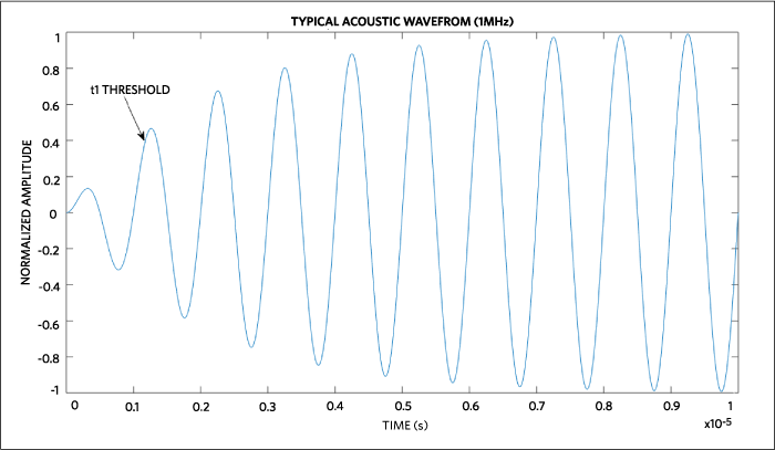
Figure 1. Normal transducer signal.
The MAX35103 is configured to identify the first cycle (t1) when the signal amplitude exceeds a programmable threshold, which in this example is 0.4. Each subsequent cycle is identified by another programmable threshold, which in this case (and the typical case) is the positive going zero crossing.
The MAX35103 can be programmed to record the time-of-flight times of a set of up to six individual waves, called the "time-of-flight waves," or "TOF waves." Typically, these waves are programmed to be those of maximum amplitude that occur after the exponential component of the signal has stabilized. The important fact to note here is that the identification of the TOF waves that are recorded into the hit-value registers are always relative in time to the t1 wave. Therefore, if the t1 wave is misidentified (e.g., the threshold isn’t met), then the TOF waves are also misidentified.
To illustrate, consider an attenuated transducer signal as seen from the receiver in Figure 2.
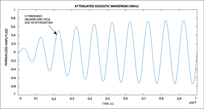
Figure 2. Attenuated transducer signal.
The actual t1 wave occurs at approximately 1µs, but since it doesn’t meet the threshold of 0.4 due to the presence of bubbles in the flow body it is not identified as t1. Instead, the subsequent wave is identified as the t1 wave since it does have the amplitude to exceed the threshold. The TOF waves are also delayed by one cycle; therefore, the hit values are larger than expected by one transducer oscillator period.
The root of the problem is that a static threshold is used to identify the first acoustic wave (t1). Ideally, this threshold (defined by bitfields C_OFFSETUP and C_OFFSETDN) should be well above the noise floor, yet low enough so that the earliest wave possible reliably exceeds this threshold. Measurements made while intermittent bubbles are passing through the flow body can cause the threshold not to be exceeded until subsequent waves of the transmission.
Detection
As described in the previous section, bubbles can attenuate the transducer signal and thereby cause the MAX35103 to recorded hit values that are delayed in time by one or more transducer oscillator periods. This can be detected programmatically by looking for shifts in the values recorded in the hit registers from one TOF operation to the next. The magnitude of the shift is always positive and always an integer number of transducer oscillator periods.
There are three ways that firmware can detect attenuation that causes time-of-flight shifts:
- Compare the time-of-flight values contained in the hit registers to expected values. The expected values could be values from recent valid TOF operations. If the difference corresponds to a sudden increase by an integer number of transducer oscillator periods, then the sample should be considered suspect.
- Compare the TOF difference value (the difference between up and down TOF measurements, which is proportional to fluid flow through the flow body) for sign reversals. Sign reversals are possible since the attenuation due to bubbles is not necessarily (and often isn’t) the same in both directions.
- Compare the t1/t2 ratio value against an expect value. This ratio typically decreases as the signal becomes more attenuated. The previous two methods are more robust in detecting attenuation, but this is a fast and simple supplementary check.
As an example, consider the following set of six hit values of a measurement unaffected by bubble attenuation:
Hit1 = 62.0µs
Hit2 = 63.0µs
Hit3 = 64.0µs
Hit4 = 65.0µs
Hit5 = 66.0µs
Hit6 = 67.0µs
These results can be validated by the following observations:
- t1/t2 ratio being as expected (from experimental results).
- The values are separated in time by the expected multiple of the oscillator periods (in this case 1 period of a 1MHz oscillation frequency).
- The values increase from earliest time-of-flight measurement to the latest.
- The values are similar to recent sample periods where the flow is not expected to have drastically changed.
Now consider the next TOF sample time in the same direction:
Hit1 = 63.2µs
Hit2 = 64.2µs
Hit3 = 65.2µs
Hit4 = 66.2µs
Hit5 = 67.2µs
Hit6 = 68.2µs
If the sampling period is small relative to the maximum expected change in flow rate, then these values suggest that signal attenuation has occurred since the values are offset in time by approximately one transducer oscillator period from the previous sample.
It is worth emphasizing that these hit values also cause the TOF average and TOF difference values to be incorrect. This coupled with the fact that attenuation due to bubbles is often not the same in both directions, it should be apparent that the TOF difference value can be wildly incorrect.
The best method of validating samples is ultimately dependent on the nature of the flow being measured and the design of the product. However, the fundamental approach described here should provide a foundation from which to begin product design.
Compensation
Once an attenuated sample is identified, there are a few possible firmware remedies that could be implemented in firmware:
- The sample is discarded and an error condition is set.
- The sample is discarded and the data point is interpolated using adjacent valid samples.
- The sample is discarded and another measurement is taken to replace it.
- The sample is corrected by "unshifting" the hit values in time according to an expected value.
It is important to note that appropriate attenuation compensation is closely related to sampling period. In cases where bubbles are common, high sample rates become necessary due to the high rate of change in fluid density caused by the bubbles. This can have negative effects on battery-powered designs.
In applications where bubbles must be tolerated, it is likely necessary to operate the MAX35103 in a nonevent-driven mode. Specifically, the host processor should start TOF measurements manually and as fast as is required to avoid nyquist aliasing due to high-frequency changes in fluid density.
Conclusion
Applications that must tolerate some amount of undissolved gases should first consider a mechanical solution, if possible. Additionally, all applications should have some mechanism of validating the time-of-flight values returned in the hit registers.