Design Note 458: Buck Converter Eases the Task of Designing Auxiliary Low Voltage Negative Rails
Introduction
Many system designers need an easy way to produce a negative 3.3V power supply. In systems that already have a transformer, one option is to swap out the existing transformer with one that has an additional secondary winding. The problem with this solution is that many systems now use transformers that are standard, off-the-shelf components, and most designers want to avoid replacing a standard, qualified transformer with a custom version. An easier alternative is to produce the low negative voltage rail by stepping down an existing negative rail. For example, if the system already employs an off-the-shelf transformer with two secondary windings to produce ±12V, and a –3.3V rail is needed, a negative buck converter can produce the –3.3V output from the –12V rail.
Leave the Transformer Alone: –3.3VOUT from –12VIN
Figure 1 shows a negative buck converter that generates –3.3V at 3A from a –12V rail. The power train (indicated by bold lines in Figure 1) includes an inductor L1, a diode D1 and a MOSFET Q1. The LTC3805-5 controller includes short-circuit protection (the current level can be precisely set), enable control and a programmable switching frequency. An internal shunt regulator simplifies biasing this IC directly from the input rail.
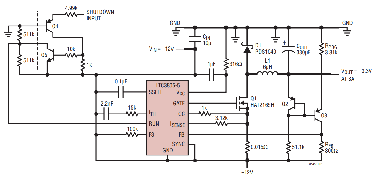
Figure 1. A Negative Buck Converter Based on the LTC3805-5 Produces –3.3V at 3A from a –10V to –14V Input.
Despite the simplicity of this topology, there are some design hurdles. The first is that the feedback loop must control a negative output voltage via the controller's internal positive reference. The second is that the on/off signal is referenced to the system ground.
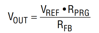
To solve the output reference polarity problem, the regulation loop uses a current mirror based on transistors Q2 and Q3. Resistor RPRG programs the current flowing into resistor RFB which sets the output voltage. In this example, when the output voltage is at the desired –3.3V, the current through the 3.31k RPRG resistor is 1mA. This current creates a 0.8V drop across resistor RFB, which is equal to the reference voltage, VREF, of the internal error amplifier:
There is also an optional on/off circuit based on transistors Q4 and Q5. If 5V is applied to resistor R8, the LTC3805-5 shuts down. Both circuits are referenced to the system ground. The voltage stress on the power train components, the transfer function and other parameters are similar to positive input voltage buck converters.
This circuit operates at 90% efficiency, as shown in Figure 2. Figure 3 shows the progressive overcurrent protection as the load current increases. The output voltage drops at loads exceeding 4.5A, and at 5A the converter enters into a short-circuit protection state where the power is limited to 0.25W. The output voltage recovers after the short-circuit is removed. In addition, the line and load regulation has a maximum deviation of less than 1%. Figures 4 and 5 show the start-up and transient response waveforms, respectively.
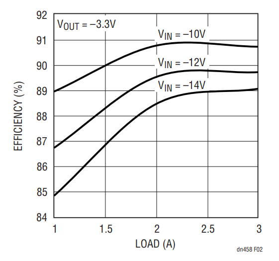
Figure 2. Efficiency vs Input Voltage and Output Current for the Circuit in Figure 1.
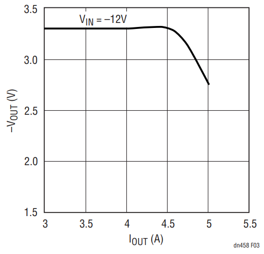
Figure 3. Output Voltage vs Output Current, at –12V Input Voltage for the Circuit in Figure 1.
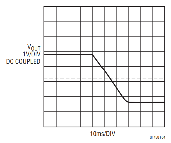
Figure 4. Start-Up into Full Load.
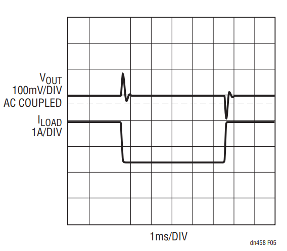
Figure 5. Transient Response for a Load Current Step from 1A to 2.5A.
Conclusion
A negative buck converter is an easier way to generate an additional negative rail in systems that already have a larger negative voltage supply. This avoids undesirable replacement of standard transformers or modular components.
作者
