AN-045: TRINAMIC Technology Access Package
The TMC2208 is an advanced 1-axis stepper driver, which supports stealthChop™ and 256 microsteps. This appnote shows how to setup the TMC2208 as a replacement of the A4988 (legacy mode).
Pin Comparison
The TMC2208 in comparison with other motor drivers comes with additional features: 256 microsteps.
An automatic current reduction reduces power dissipation and cooling requirements. Per default, the stand still current reduction is enabled by pulling PDN UART input to GND.
The UART single wire interface allows control of the TMC2208 with any microcontroller UART. This gives the possibilty to program the TMC2208 and add additional features such as full 256 Microsteps control (not only interpolation). UART is not available in legacy mode.
An active DIAG output shows that the driver cannot work normally.
The INDEX output signals the microstep counter zero position, which occurs once per electrical revolution/- four fullsteps. In combination with a mechanical home switch, a more precise homing is enabled.
The TMC2208 is able to control the motor with 256 microsteps per fullstep. In legacy mode the TMC2208 will interpolate received step signals to 256 microsteps.
For optimized performance in legacy mode it is recommended to consider the hints as shown in the comparison below:
| Pin | A4988 Number |
TMC2208 Number |
Hints for series using TMC in legacy mode |
| 1 | OUT2B | OB2 | - |
| 2 | ENABLE | ENN | - |
| 3 | GND | GND | - |
| 4 | CP1 | CP0 | - |
| 5 | CP2 | CPI | Tie to CPO using 22nF (not 100nF) |
| 6 | VCP | VCP | - |
| 7 | - | - | - |
| 8 | VREG | 5VOUT | - |
| 9 | MS1 | MS1 | (a) |
| 10 | MS2 | MS2 | (a) |
| 11 | MS3 | DIAG | Diagnostics output. High level upon driver error. Reset by ENN = high. (b) |
| 12 | RESET | IndexX | Configurable index output. Provides index pulse. (c) |
| 13 | ROSC | CLK | CLK input. Tie to GND using short wire for internal clock or supply external clock. |
| 14 | SLEEP | PDN UART | Power down not control input (low=automatic standstill current reduction). Optional UART Input/Output. Power down function can be disabled in UART mode. |
| 15 | VDD | VCC IO | - |
| 16 | STEP | STEP | - |
| 17 | REF | VREF | (d) |
| 18 | GND | GND | - |
| 19 | DIR | DIR | - |
| 20 | - | - | - |
| 21 | OUT1B | OA2 | - |
| 22 | VBB1 | VS | - |
| 23 | SENSE1 | BRA | - |
| 24 | OUT1A | OA1 | - |
| 25 | - | - | - |
| 26 | OUT2A | OB1 | - |
| 27 | SENSE2 | BRB | - |
| 28 | VBB2 | VS | - |
I/O Config: Using 2,4,16 microsteps won’t require any change. See table 2 below. Different microstep configurations are marked bold:
| TMC2208/A4988 MS1 |
TMC2208/A4988 |
A4988 MS3 |
A4988 Microsteps |
TMC2208 Microsteps |
| low | low | low | 1 | 8 |
| high | low | low | 2 | 2 |
| low | high | low | 4 | 4 |
| high | high | high | 16 | 16 |
With default settings the TMC2208 will interpolate the microsteps set by the I/O configuration pins to 256 microsteps.
TMC2208 doesn’t use third config pin for external microstep configuration, instead this pin offers optional diagnostic function. This is an output pin and should be set as input in the MCU, leave open if unused.
INDEX pin is an output pin and should be set as input in the MCU, leave open if unused.
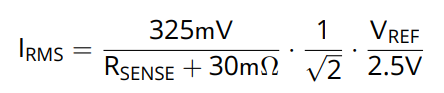
Analog reference voltage for current scaling or reference current for use of internal sense resistors (optional mode). A voltage between 0V and 2.5V linearly scales the current between 0 and the current scaling defined by the sense resistor setting. Adjust sense resistors to motor current IRMS:
Application Example
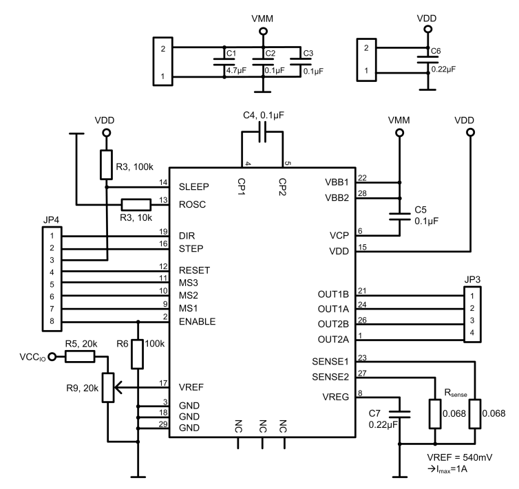
Figure 1a. Stepstick schematic.
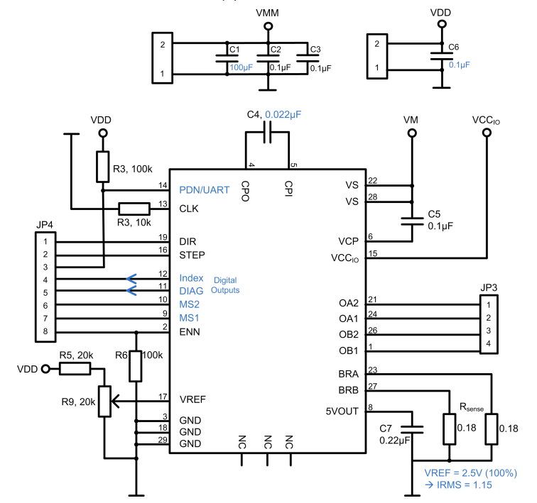
Figure 1b. Stepstick schematic.
As an application example a schematic of an StepStick is depicted at the top (subfigure 1a). The TMC2208 is inserted and used in legacy mode (subfigure 1b). Recommended changed parts are marked blue. The Pins PDN/UART, INDEX, DIAG, MS2, MS1 feature additional or slightly changed functions as discussed in table 1.
The sense resistor should be chosen according to the motor current of the application. Table 3 shows the relation between sense rensistor and current for VREF = 2.5A after equation 1. For the application example RSENSE is set to 0.18Ω which allows to control motor currents up to 1.2A.
| RSENSE | RMS current[A], VREF = 2.5V or open | Fitting motor type (examples) | ||||
| 1.00 | 0.22 | 300mA motor |
||||
| 0.82 | 0.27 | |||||
| 0.75 | 0.29 | |||||
| 0.68 | 0.32 | 400mA motor | ||||
| 0.5 | 0.43 | 500mA motor | ||||
| 0.47 | 0.46 | |||||
| 0.39 | 0.55 | 600mA motor | ||||
| 0.33 | 0.64 | 700mA motor | ||||
| 0.27 | 0.77 | 800mA motor | ||||
| 0.22 | 0.92 | 1 A motor | ||||
| 0.18 | 1.09 | 1.2A motor | ||||
| 0.15 | 1.28 | 1.5A motor |
||||
| 0.12 | 1.53* | |||||
| 0.10 | 1.77* | |||||
| * Value exceeds upper current rating, scaling down required, e.g. by reduced VREF. | ||||||
作者
