Understanding Challenges in USB Charger Design for Automotive Applications
要約
Recent advancements in the automotive infotainment market demand high-efficiency and low-footprint power delivery (PD) solutions. The inclination towards a reduction in bill of materials has driven USB power applications to integrate more features and responsibilities into a single IC. The proliferation of battery-powered portable devices has resulted in an increase in the number of USB receptacles or ports in an automobile to charge the batteries of the devices. This application note describes the design and system challenges associated with USB chargers in automotive applications.
Introduction
The universal serial bus (USB) is an interface standard for supplying electrical power and communication between peripherals and modern computing devices. It was developed by a group of companies in 1991 and is currently overseen by the USB-Interactive Forum (USB-IF). This interface standard makes it easier for manufacturers as well as consumers to share data and power between computers and peripherals, which includes but is not limited to keyboards, mice, mobile phones, tablets, etc. The USB standard is continually updated by USB-IF to include extra features and since its introduction, there have been the following standards – USB1.x, USB2.x, USB3.x with the latest being USB4. x. These specifications vary in communication speeds and features summarized below:
- USB1.x: Data speeds of up to 1.5Mbps and 12Mbps.
- USB2.x: Data speeds of 1.5Mbps, 12Mbps, and 480 Mbps.
- USB3.x: Data speeds of 5Gbps, 10Gbps, and 20Gbps.
- USB4.x: Data speeds of up to 40Gbps (Superspeed, Thunderbolt 3/4).
The USB standard also defines different connectors that are used and involve special markings to indicate the maximum communication speeds that can be attained. These connectors are broadly classified into Type-A, Type-B, and Type-C with various subcategories within them based upon size.
The latest introduction into the market has been USB Type-C, known for its ability to function irrespective of the orientation of the connector while plugging it into the USB port. A typical USB Type-C receptable in a car is shown in Figure 1. However, USB ports and connections do not work as simply as is perceived. Until the introduction of Type-C and USB 3.x and further, the USB connectors Type-A and Type-B primarily had 4 wires, VBUS, GND, D+, and D-. These, as the names suggest, were used to supply power to the peripheral (VBUS, GND) and to communicate data between the peripheral and the host (D+, D-). A Type-C receptacle port is shown in Figure 2.
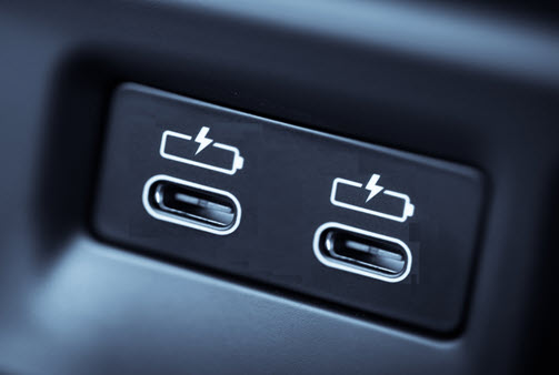
Figure 1. USB Type-C receptacle in a car.
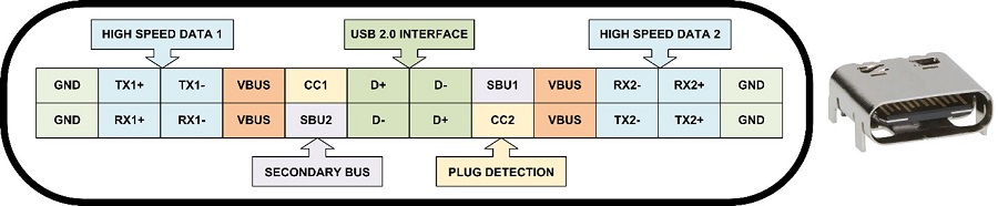
Figure 2. USB Type-C receptacle.
In a USB Type-C solution, where a dedicated microcontroller is used for detection and protocols, the use of multiple dedicated microcontrollers for each USB receptacle increases the cost and size of the solution. This challenge is solved by using a single microcontroller, the USB Type-C Policy Manager (TCPM), which operates as a master as well as multiple USB Type-C port controllers (TCPC) that drive the USB receptacles that operate as slaves. The TCPM and TCPC communicate using I2C.
Challenges in Automotive Application
Automotive IC designs are required to meet the Automotive Safety Integrity Level (ASIL) standards, which is a risk classification system defined by ISO26262. There are four ASIL levels, A to D, where A represents the lowest degree and D is the highest degree of automotive hazard. Critical systems such as airbags, power steering, and anti-lock brakes are designed with ASIL-D standards. USB applications in automobiles primarily focus on portable device charging. Typically, USB chargers are not designed with ASIL standards as they do not directly impact critical systems. Despite this, USB chargers are designed to withstand harsh automotive environments. The following section discusses various challenges and describes multiple solutions.
High-Temperature Environment
USB charging ports are typically located near the dashboard or armrest. The power conversion circuit, along with the controller, is packed in a tight plastic enclosure with limited to no airflow behind the infotainment head unit. Recent applications demand high-speed battery charging for phones or laptops which is attained by using high-power DC-DC conversion circuits. This power converter is designed to have high efficiency and low package thermal resistance. For example, consider a 100W USB charger with 97% efficiency, which dissipates 3W power loss. If a package with ?J = 27°C/W is used at an ambient temperature (TA) of 30°C, the power converter board operates at 111°C (30 + 27 × 3) in a closed enclosure, which is hot. Typically, automotive ICs are designed to operate in the -40°C to +125°C temperature range. The design becomes challenging if dual USB ports are implemented where the enclosure temperatures become dangerous. This issue is solved by using a very high efficiency power converter, a heatsink, or by limiting the power capability (1 × 100W, 1 × 50W, or 2 × 50W) when two ports are used simultaneously. A thermal warning or shutdown circuit implemented inside the power converter IC is used for safety.
Voltage-Drop on Charging Ports
The USB ports located on the center console or near the rear passenger seats (as shown in Figure 3) are connected to the output of the power converter using a long cable. This power converter is present in the infotainment head unit in the dashboard. A voltage drop is observed at the end of the cable on the USB receptacle while charging since these cables have a finite resistance. For example, the output voltage of 5V with a 5A current in a 100m? cable has a 500mV voltage drop at the receptacle. This violates the USB (3.0) standard that requires the connector voltage to be within ±250mV range (±5%). Large voltage swings are observed on the receptacle during load transients and when the device connects or disconnects. This issue is solved by implementing a voltage drop compensation where the output voltage of the power converter is increased proportionally to the output current as shown in Figure 4. The control scheme includes positive feedback where the voltage is increased for increased current where stability challenges often arise. This method is used to compensate for voltage drops due to resistances from the PCB traces and connectors. This gives an accurate charging voltage at the device end. Additionally, a sense resistor added to detect the output current creates additional voltage drop and power loss. Moreover, voltage drop compensation introduces a large voltage drop during load transients. The long power cable also includes inductance, in addition to its resistance, which leads to large voltage drops during fast load transients.
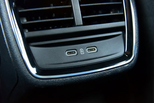
Figure 3. USB ports in a car's backseat.
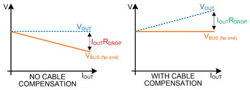
Figure 4. Cable voltage drop compensation.
Cable Ground Short to Cigarette Lighter Port
Automobiles have cigarette lighter ports with 12V connected to the battery as shown in Figure 5. It is a common practice for one end of the charging cable to always be connected to a USB receptacle while the other device is floating or disconnected. The device end of the cable has a metallic surface internally connected to the grounded shield of the cable. This exposed end can contact the 12V cigarette lighter port causing a short between the 12V battery and cable ground. This condition results in damaging current flow to the consumer cable and the cigarette lighter wiring. A ground switch is used on the USB charger port side to disconnect the ground to the shield (Figure 6). A cable shield short to battery event is detected and the shield ground switch is turned off to protect the USB charger, cable, and cigarette lighter. This ground switch is required to have low RDSON to limit the cable ground voltage level (shift), which allows USB communication and detection. Additional protection circuits are required to protect the microcontroller that drives either D+/D- pins or CC1/CC2 pins.
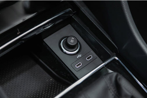
Figure 5. A 12V cigarette lighter in an automobile.
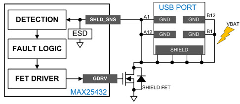
Figure 6. Cable shield short to a 12V cigarette lighter.
Frequent Line Transients During Start-Stop and Cold-Cranks
The DC-DC converter used for USB ports in high-voltage automotive applications is typically connected to a lead-acid battery. This battery operates in the 9V to 16V range with voltage transients that can go as low as 4V and as high as 40V. Cold-cranking occurs when the engine is cranked in cold weather with a partly charged battery, and the engine oil has become very thick. The engine cranking requires the starter to deliver more torque, which, in turn, needs more current from the battery. This large current load causes a brief "dip" in supply voltage, a dip that can depress the voltage from a nominal 12V to less than 5V. This reduction can last for several hundreds of milliseconds. Once the engine starts, the voltage returns to its nominal value. The voltage profile for warm cranking is similar to cold-cranking with different voltages and timing. The battery supply voltage transient behavior caused by cold and warm cranking is shown in Figure 7. The auto start-stop is a common feature in newer automobiles where the engine is shut off for a brief time while waiting at the traffic light or in traffic jams. This frequent start-stop causes the battery voltage to droop and has similar transient behavior as a cranking. As such, USB charger designs should handle high input voltages as well as load dump events through the vehicle's lifetime.
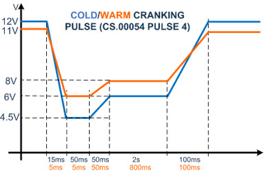
Figure 7. Battery voltage transient due to cold and warm cranking [1].
High-Voltage Environment and ESD Requirements
High-speed communication in USB is supported with D+/D- data pins. These pins are driven by a microcontroller IC or power delivery (PD) controller that operates with absolute maximum voltage ratings of 3.3V/5.5V. The data pins on the USB cable and receptacle are exposed to a high-voltage environment such as a cigarette lighter port at 12V, and its adjacent VBUS pin that can be as high as 21V. To protect the low-voltage microcontroller, the data pins should be isolated with high-voltage FETs. Similar conditions and requirements apply to CC pins. These pins should also be protected from ESD events by implementing automotive-grade ESD protection such as ±15kV Air/±8kV Contact in accordance with IEC 61000-4-2 and ISO 10605. The isolation high-voltage FETs and ESD structure should be designed such that the communication eye diagram is not corrupted. In automotive applications, the receptacle-side USB port pins are called HVD+, HVD-, HVCC1, and HVCC2 for D+, D-, CC1, and CC2, respectively.
MAX25432/MAX25430
The MAX25432 integrates an automotive-grade 100W buck-boost controller with a full-range 3.3V to 21V programmable power supply (PPS) at up to 5A[2]. The MAX25430 is a 100W buck-boost controller with a fixed output voltage of 5V, 9V, 15V, and 20V at up to 5A for USB PD applications [3].
High-temperature issues due to tight plastic enclosures with limited to no airflow is solved in the MAX25432/MAX25430 by implementing thermal shutdown. Thermal shutdown protection limits the temperature the device is allowed to reach before forced shutdown. If the die temperature exceeds +165°C, the device shuts down and requires it to cool down. Once the device has cooled down by 15°C, the device is automatically enabled again. The thermal overload protects the device in the event of overheating.
The cable voltage drop in the rear passenger seats due to long cables is solved by implementing a voltage drop compensation, where the output current is sensed and feeds back the current information to the internal feedback block of the converter. The MAX25432/MAX25430 compensates voltage drops for up to 516m? from parasitic resistance present from the OUT pin to the user cable. This includes but is not limited to the USB captive cable, PCB trace, and inline connectors. The cable compensation is designed for use in the constant voltage region at up to 5A. Cable compensation stays active upon entry into the PPS current limit region in the MAX25432.
The damage associated with a cable shield short-to-battery event through a 12V cigarette lighter port is avoided in the MAX25432/MAX25430 by implementing a detection and control scheme. When a Type-C attachment is present and the cable shield contacts the 12V port, a large surge current flows through the ground isolation FET's RDSON to ground. This surge current develops a voltage across it and is sensed through a sense pin (SHLD_SNS). When the sense voltage exceeds a certain voltage threshold or slope, the fault-detection comparator is triggered. After a debounce period, the FET is switched off and the fault condition is reported.
The MAX25432/MAX25430 is designed for 4.5V to 36V (40V load-dump) input voltage and allows operation in "warm-crank" and start-stop conditions. The designer must consider the current limit associated with the input fuse.
The MAX25432/MAX25430 provides high-voltage protection for the USB PD or TCPM controller from events at the receptacle or captive cable. A 24V DC protection is implemented on data and CC pins. The high-voltage D+/D- pins (HVD+/HVD-) and CC pins (HVCC1/HVCC2) are monitored and protected for overvoltage conditions such as ESD or short-to-battery/VBUS events. The MAX25432/MAX25430 includes automotive-grade ESD protection on the USB HVD+, HVD-, HVCC1, HVCC2, and Shield sense pins complaint to (a) ±15kV Air-Gap /±8kV Contact Discharge IEC 61000-4-2, (b) ±15kV Air-Gap /±8kV Contact Discharge ISO 10605. All other pins are ESD protected with ±2kV human body model (HBM). The MAX25410 is a dedicated port protector for the data and CC pins [4].
{{modalTitle}}
{{modalDescription}}
{{dropdownTitle}}
- {{defaultSelectedText}} {{#each projectNames}}
- {{name}} {{/each}} {{#if newProjectText}}
-
 {{newProjectText}}
{{/if}}
{{newProjectText}}
{{/if}}
{{newProjectTitle}}
{{projectNameErrorText}}
最新メディア 21


