New Instrumentation Amplifier: Single-Resistor Gain Set and Precision Front End Make Accuracy Easy
New Instrumentation Amplifier: Single-Resistor Gain Set and Precision Front End Make Accuracy Easy
2000年05月01日
The LT1168 is a low power, single-resistor gain-programmable instrumentation amplifier that is easy to apply. It is a pin-compatible upgrade for the AD620 (and the INA118 with a resistor-value change) and is available in C and I grades. With negligible 60µV (Max) offset voltage and ultrahigh 1TΩ input impedance, it can sense bridges with source impedances from 10Ω to 100k without degrading the signal. Its 120dB CMRR at 60Hz (AV = 100V) is achieved even with a 1k source impedance imbalance. Matching the LT1168’s CMRR using discrete op amps would require the use of 0.001% resistors. The LT1168’s robust inputs meet IEC1000-4-2 Level 4 ESD tests with the addition of two external 5k series resistors. These 5k resistors will contribute only a negligible 6µV of DC error.
Typical Application: Absolute Pressure Meter (Barometer)
Figure 1 shows just how easy it is to apply the LT1167. The LT1097, in conjunction with the LT1634-1.25 reference and R1, provides a precision current drive for the bridge. D1 ensures that the common mode input range of the LT1097 is not exceeded over temperature. With the current drive and the sensor bridge in place, the rest of the circuit is composed entirely of the LT1167 and its gain-set resistor, R2. The sensor gives a full-scale output of 50mV (±1%) at 30psi (just over two atmospheres) with a 1.235V reference. With a 1.25V reference, the full-scale output value scales to 50.61mV. In order to get a convenient and easily read output of 100mV per 1psi, R2 should be chosen to set the gain to 3V/.05061V = 59.28. Or, with 2.036 inches of mercury equal to 1psi (referred to 39°F), change R2 to set a gain of 120.7 for a convenient output of 100mV per 1inHg. Or, again, with 6.8947kPascals equal to 1psi, set the gain to 408.7 for an output of 100mV per kiloPascal. The single-resistor gain adjustment makes it easy to accommodate the desired units effortlessly.


Figure 1. Simple barometer.
Setting the Gain
The relation between the LT1168 gain and the gain-set resistor is given by the following equations: RG = 49.4kΩ/(Gain – 1), and equivalently, Gain = (49.4kΩ/RG) + 1. In order to take advantage of the high CMRR without taking gain, simply do not connect an RG. This configures the LT1168 as a precision, buffered, unity-gain difference amplifier. If precision gain is desired, use a 0.1% precision resistor in order not to degrade the 0.1% gain error specification of the LT1168. To target the desired gain exactly, pick a standard 0.1% value that is slightly smaller than required. Then, in order to “top up” the total RG to the required value, use a small value standard 1% resistor in series, as shown in Figure 2. As long as the 1% resistor is a relatively small value, say 1/20 of the 0.1% value, the overall precision will not be degraded. Table 1 shows practical resistor values for the gains specified above. Note that most transducers do not have 0.1% accurate sensitivity anyway, so most applications would use a 1% resistor and then perform a two-point calibration on the overall system.


Figure 2. Targeting gain precisely.
| Desired Gain | RG (Theoretical) | RG1 0.1% | RG2 1% "Top-Up" | Resultant Gain |
| 59.28 | 847.63Ω | 845Ω | 2.61Ω | 59.28 |
| 102.69 | 412.72Ω | 412Ω | 1Ω | 120.61 |
| 408.72 | 121.62Ω | 121Ω | 0Ω | 409.62 |
Achieving Large Output Swings
Figure 3 shows the block diagram of the LT1168. Note that the last stage is a unity-gain difference amplifier. This means that the output voltage (across the Output and the Ref pins) will appear internal to the LT1168 across nodes Vx and Vy, centered around the common mode input voltage (minus one VBE). In order to support full output swings, whether due to high applied gains or large differential inputs, the common mode input voltage should not be too close to either rail. For example, if the inputs are centered around ground and the Ref pin is grounded, then under excitation Vx and Vy will swing around ground (minus one VBE) and the output swing will be limited by the normal output stage limitation of about 1.2V from either rail. However, if the common mode input voltage is at 10V on ±15V supplies, Vx and Vy will swing around 9.3V. In this case, the output swing will be limited by the outputs of the intermediate amplifiers, A1 and A2, as they reach their upper limits about 1V from the rail. Thus, the final output swing in this case will be limited to ±4.6V even though the supplies are ±15V. With regard to the lower rail, if the common mode input voltage is at –10V on ±15V supplies, then VX and VY will swing around –10.7V. The final output swing in this case will be limited to ±3.3V even though the supplies are ±15V.


Figure 3. LT1168 block diagram.
As a rule of thumb, in order to achieve the full output swing, keep the common mode input voltage within the middle one-third of the supplies. For example, in the case of Figure 1, with gain = 408.7, the full-scale output voltage at 30psi (204.4kPa) would be 20.44V. Providing the LT1168 with +24V/–5V supplies and, given that the bridge section of the sensor typically has about 3V of excitation across it, replacing D1 with a 12V Zener diode will approximately center the common mode input voltage. This allows the LT1168 to achieve full 0V (vacuum) to 20.44V (204.4kPa, or about 2.2 atmospheres) output swing. For information on using the LT1168 on a single 5V supply, see “Designing the LT1167 Instrumentation Amplifier into a Single 5V Supply Application,” in Linear Technology IX:2 (June 1999).
AC Performance at Low Power
The LT1168 is not limited to DC and low frequency applications. Figures 4 and 5 show the frequency response and common mode rejection ratio of the LT1168 for various gains. The high frequency performance renders the LT1168 applicable in accelerometer and balanced audio line receiver applications, for example, in addition to the usual slower applications. This AC performance is achieved with a low supply-current budget of only 0.5mA.

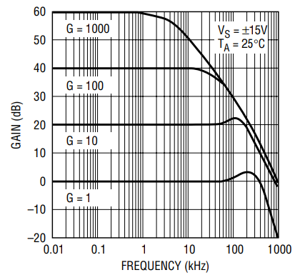
Figure 4. LT1168 gain vs frequency.


Figure 5. Common mode rejection ratio vs frequency (1k source imbalance).
Conclusion
The LT1168’s precision front end and simple gain programmability make accuracy easy to achieve. The AC performance of the internal amplifier results in both extended differential mode bandwidth and excellent common mode rejection. Good common mode rejection is essential for extracting signals from a hostile world of interference.
著者について
Glen Briseboisは、アナログ・デバイセズのシグナル・コンディショニング・グループ(シリコン・バレー)に所属するアプリケーション・エンジニアです。カナダのアルバータ大学で物理学と電気工学の学士号を取得しています。同大学を卒業後、トラピスト修道院とカルトゥジオ修道院で数年間、修道生活を送ろうとしました。しかし、その間も「回路」のことが頭から離れませんでした。現在は結婚し、子どもたちと一緒に幸せに暮らしています。業務の大半は回路に関連...
この記事に関して
{{modalTitle}}
{{modalDescription}}
{{dropdownTitle}}
- {{defaultSelectedText}} {{#each projectNames}}
- {{name}} {{/each}} {{#if newProjectText}}
-
 {{newProjectText}}
{{/if}}
{{newProjectText}}
{{/if}}
{{newProjectTitle}}
{{projectNameErrorText}}
最新メディア 21