Monolithic Ideal Diode Prolongs Battery Life
Introduction
Many consumer electronic devices rely on batteries and wall adapters for supplying power for portable and hand held applications. These devices must rely on some method of automatically and smoothly switching between the battery and the wall adapter. The LTC4411 is a low loss ideal diode that simplifies the implementation of PowerPath™ control circuitry. With the LTC4411 it is possible to build an entire power management solution in a 2mm × 3mm footprint.
The LTC4411 is a low-voltage (2.5V to 5.5V) monolithic (no external P-channel MOSFET needed) ideal diode. It is pin-compatible with the LTC4412 ideal diode controller (except the LTC4411 omits the pin that the LTC4412 provides to drive the gate of an external P-channel MOSFET). The LTC4411 provides a low forward voltage drop, typically less than 50mV when conducting, and a low RDS(ON), below 140mΩ, that is well suited to providing a low cost PowerPath management solution in portable battery applications. The LTC4411’s compact design solution is capable of supplying up to 1.6A of continuous current from a small 5-pin ThinSOT™ package. The LTC4411 also provides power monitoring and control circuitry for integration within other parts of the power management system.
The LTC4411 is ideally suited to applications that require seamless operation when plugging in or disconnecting a wall adapter or other auxiliary power source. Figure 1 shows an application where the LTC4411 automatically disconnects the system load from the battery when the auxiliary source is attached, and then reconnects the battery to the load when the auxiliary source is removed. In this configuration, no current is drawn from the battery when auxiliary power is available, and no potentially damaging reverse current flows into the battery when the auxiliary source is present. When the auxiliary source is disconnected, the LTC4411 automatically reverts to providing system power from the battery, typically in as little as 9µs. This quick response time means that the load should see uninterrupted, glitch-free power (due to the charge stored in COUT).


Figure 1. Automatic PowerPath control using an LTC4411 and a Schottky diode
The low forward voltage drop, low RDS(ON), and low reverse leakage current of the LTC4411 offer several benefits. The tiny forward voltage drop directly results in extended battery life. The low RDS(ON) reduces power dissipation; further enhancing battery performance. The very low reverse leakage current, when compared with a Schottky diode, is also beneficial in several applications; where leakage current into a battery from a reverse biased Schottky diode could cause damage or failure.
The LTC4411 increases system reliability by including features for short circuit protection, thermal management, and system-level power management and control. The LTC4411 provides an adapter present signal pin to indicate conduction status, and an active-high disable input pin to control the operation of the LTC4411. These two pins support logic monitoring and automatic power control functions.
How It Works
Figure 2 shows an application of the LTC4411 as an automatic power switch between a wall adapter and a battery. Here the LTC4411 is configured to automatically disconnect the load from the battery cell(s) when the wall adapter (or other power source) is applied. The operation of this circuit is described with the aid of Figure 3, where the supply inputs are slowly ramped to illustrate how the LTC4411 functions. First the battery input is ramped up from 0V while the auxiliary input is held at 0V (time A1). Once the battery voltage exceeds the Under-Voltage Lock Out (UVLO) threshold (A2), the LTC4411 begins to conduct in forward regulation mode, pulling the output voltage up to within 20mV of the battery voltage (the voltage drop across the LTC4411 depends on the load current). During the forward regulation mode of operation (from time A2 to B2), the STAT pin will be an open circuit and the 470kΩ resistor pulls the STATUS voltage up to VOUT. Alternately, this resistor may be tied to any voltage, VCC, up to 6V as shown in Figure 1, regardless of the voltage at IN.


Figure 2. Automatic power switching between a battery and an auxiliary input using an LTC4413 and an external P-channel MOSFET


Figure 3. Operation waveforms for the LTC4411
As the wall adapter or other auxiliary supply voltage is ramped up from 0V (time B1) through a Schottky diode, the LTC4411 automatically senses when the voltage at its output rises to within VRTO (reverse turn-off voltage, 14mV maximum) of the voltage at it’s input (time B2). At that point, the LTC4411 enters into the reverse turn-off mode of operation and the STAT pin sinks 10µA of current to indicate that the auxiliary supply is present. While in reverse turn-off mode, the LTC4411 turns off, and isolates the battery from the load. The battery voltage is raised slightly as it no longer supplies power to the load (B3). At the same time, while the LTC4411 is in reverse turn-off mode, all the power to the load is delivered from the auxiliary supply through the external diode; and no current is drawn from the battery and delivered to the load. Note that the LTC4411 actually goes into reverse turn off mode while the voltage at IN is still above the voltage at OUT, VRTO = VOUT – VIN is a negative quantity, typically as low as a few mV. This guarantees that the ideal diode is shut off when an auxiliary power source pulls the voltage at OUT to within a mV of the voltage at IN.
The external Schottky diode is used to protect against auxiliary input faults. A silicon diode could be used instead of the Schottky, but with higher power dissipation due to the higher forward voltage drop. Of course, for even better performance, a second LTC4411 could also be used instead of the external Schottky.
The LTC4411 provides a low RDS(ON) of only 140mΩ (100mΩ typical) for load currents from 50mA up to a minimum of 1.0A. As the load current increases further, the forward voltage drop increases until the current limit threshold is passed; at which point the LTC4411 fixes the output current at the over current maximum, IOC. This current limit feature protects the LTC4411 against inadvertent shorts to ground.
Low Loss Automatic PowerPath Control
Figure 2 is similar to the circuit of Figure 1 in that it controls automatic switchover of a load between an auxiliary input and a battery. The difference is that this circuit features lower power loss in the auxiliary path, a result of replacing the Schottky diode in Figure 1 with a P-channel MOSFET. The STAT pin is used to turn on this MOSFET once the OUT voltage exceeds the IN voltage by 20mV. When the auxiliary voltage is applied to the drain of the P-channel MOSFET, the drain-to-source diode within the MOSFET turns on first, pulling the OUT voltage up. Once the OUT voltage exceeds the IN voltage, the LTC4411 pulls down the STAT voltage, turning on the P-channel MOSFET. Once the MOSFET turns on, the voltage drop across it can be very low, depending on the MOSFET’s RDS(ON) characteristics.
Automatic Load Sharing
The precisely controlled ideal diode behavior allows for current balance when charging or discharging multiple batteries with a single source or load, allowing for efficient load sharing between batteries of different strengths and/or capacity. For example, Figure 4 shows multiple LTC4411s configured in an automatic load sharer. In this example, the battery with the higher voltage supplies all of the power to the load, and is discharged until both batteries have the same voltage, at which point both batteries supply power to the load, and discharge according to their capacity.


Figure 4. Automatic load sharing with two LTC4411s
Multiple Battery Charging
Another example is shown in Figure 5, where the LTC4411s are used to allow multiple batteries to be charged from a single battery charger. In this second example, one or both batteries can be charged regardless of the state of charge of the other battery. Whichever battery has the lowest voltage receives the charge current until both battery voltages are the same. Then, both batteries are charged simultaneously. One advantage of this method is that because of the capacitive nature of batteries, whichever battery has the highest capacity receives proportionately higher current from the charger. For Li-Ion batteries, both batteries achieve the float voltage minus the forward regulation voltage drop of 20mV. This can be extended to any number of batteries. The STAT pins of the LTC4411s reveal which of the batteries are being charged.

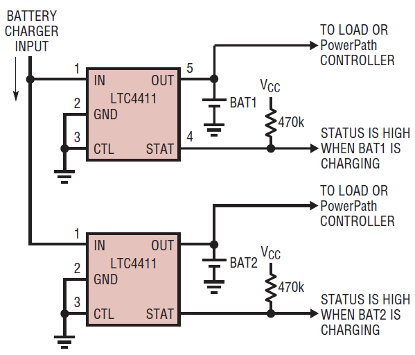
Figure 5. Multiple batteries charging from a single battery charger using multiple LTC4411
High-Side Power Switch
Figure 6 illustrates an application circuit for a logic controlled high-side power switch. When the CTL pin is a logical low, the LTC4411 turns on, supplying current to the load. When the CTL pin is a logical high, the LTC4411 turns off and denies power to the load. If the load is powered from another (higher voltage) source, the supply connected to IN remains disconnected from the load.


Figure 6. High-side power switch using an LTC4411
Conclusion
The LTC4411 ideal diode provides a simple and efficient single-IC solution for low-loss PowerPath management. This device is ideal for battery-powered portable devices—it can extend battery life, significantly reduce self-heating, and reduce circuit size with its 5-lead ThinSOT package and minimal external parts count.
著者について
最新メディア 21